Experimenting with the fundamentals of electrical and electronics is always interesting. Presented here is an electronic circuit that demonstrates Faraday’s law of electromagnetic induction and gives musical output. The law talks about electromagnetic induction and production of electromotive force (EMF) across a conductor when it is exposed to a varying magnetic field.
To experience this, place a stretched copper wire near a magnet. When you pluck the wire and it vibrates, EMF is produced in the copper wire and it produces musical notes.
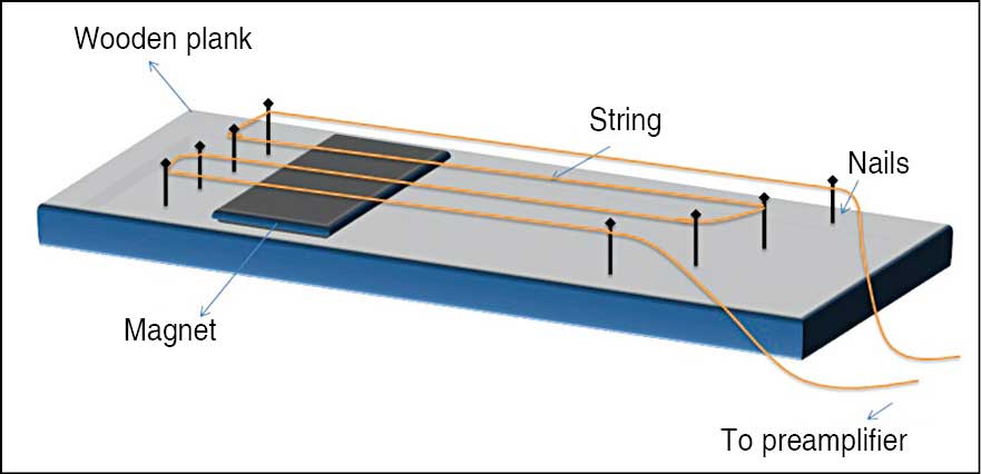
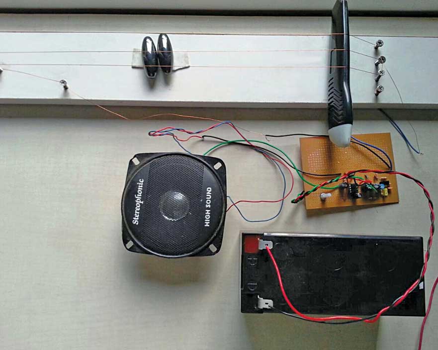
 You can make an amateur guitar with a copper string and magnet as shown in Fig. 1. While strumming the string, a small voltage is produced due to Faraday’s law. When this voltage is amplified, you can hear a pleasant sound from the speaker connected to the power amplifier. The author’s prototype is shown in Fig. 2.
Circuit and working
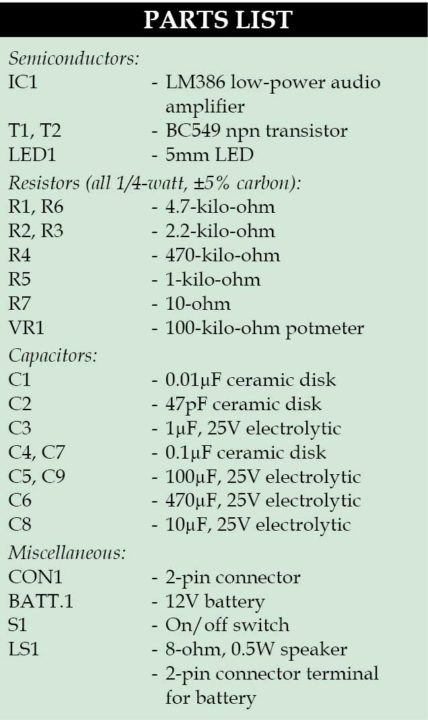
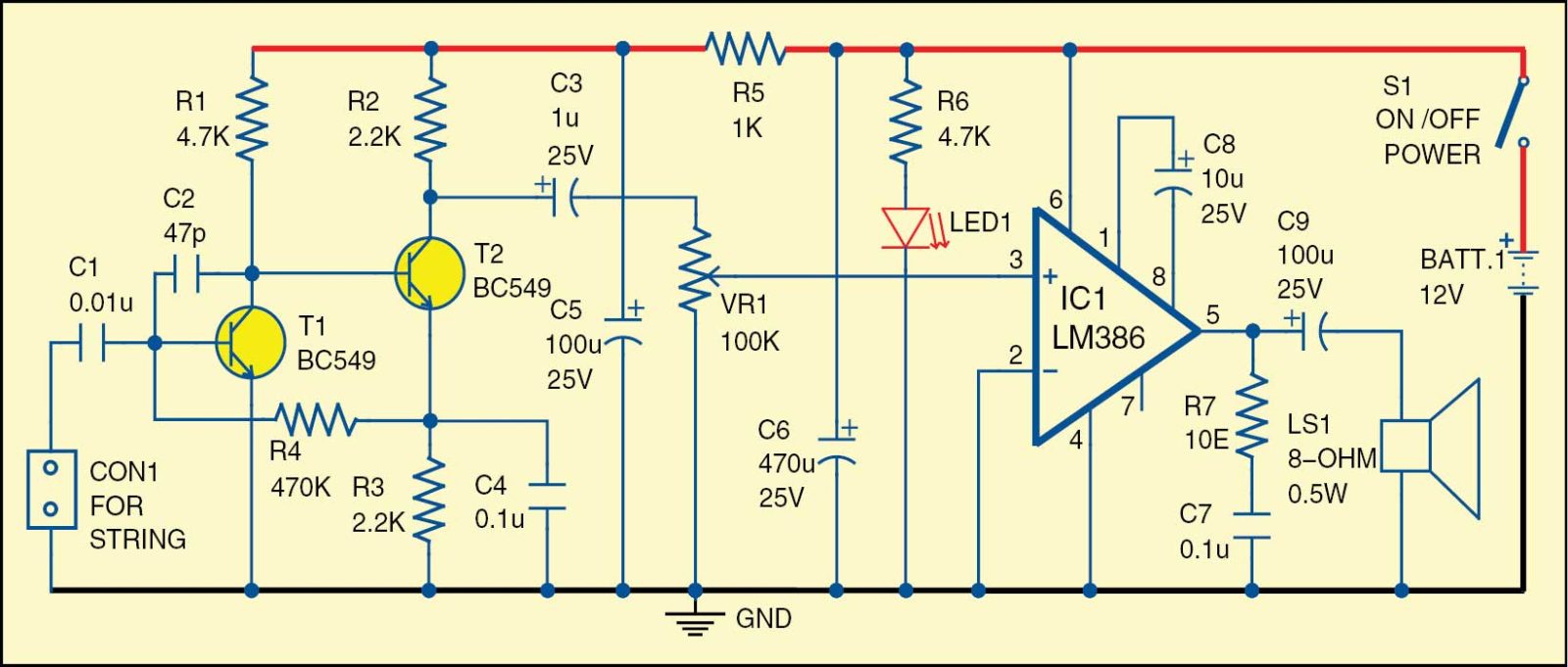
Circuit diagram of Faraday’s guitar is shown in Fig. 3. It is built around transistors BC549 (T1 and T2), low-power audio amplifier LM386 (IC1), a speaker (LS1) and a few other components. The circuit is powered by 12V battery. An on/off toggle switch (S1) is used to switch on the circuit.
The two-stage preamplifier is designed with BC549 transistors to amplify the low signal produced by guitar string. Voltage produced by the string will be in the range of ~3mV and the preamplifier amplifies the signal further to ~20mV. Resistors R1, R2 and R4 form the biasing circuit to the transistors. Capacitors C1 and C3 are bypass capacitors that allow sound signals and block DC components. Resistor R5 and capacitor C5 form an RC filter for the power supply of the preamplifier circuit.
LM386 (IC1) is a low-voltage audio power amplifier, which is suitable for battery-powered devices for hobby projects. Capacitor C8 between pin 1 and pin 8 decides the gain of the amplifier, and here it is set to 200.
Volume control VR1 is connected between output of the preamplifier and input of the power amplifier. For testing, connect the string to the preamplifier circuit and power up by closing switch S1. If you strum the string, you will hear guitar notes from the speaker. Ensure there is right tension on the strings so that the longer tone notes are achieved. You can have different string lengths so that distinct tones could be heard from each string.
Construction and testing
A single side PCB for Faraday’s guitar circuit is shown in Fig. 4 and its component layout in Fig. 5. Enclose the PCB in a suitable box and place it near the guitar.
For construction of the guitar, take a wooden plank measuring approximately 10cm×30cm and put four nails on either side as shown in Fig. 1. Tie a copper wire (string) between the nails with correct tension. The copper wire can be taken out from any transformer with 500mA secondary rating.
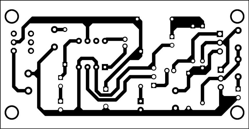
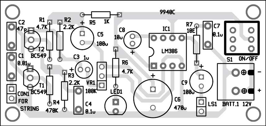
Download PCB and Component Layout PDFs: click here
Ensure that a single string is passed between all the nails without joints or breaks. Place a magnet on the wooden plank roughly below the middle of the string and ensure the gap is small between the string and the magnet. The produced EMF depends on the air gap between the magnet and the string. If the magnet touches the string, it may obstruct the vibration of the string and the produced EMF would be low. If the gap is too much then, due to weak magnetic linkage, EMF will be lower. Therefore keep the magnet as close as possible to get higher EMF.
Feel interested? Check out more electronics projects.
The original article was published in November 2015. The article has been updated since then.


hi, can i please get the kit for the for the above project.
if possible please tell us as early as possible
waiting for the reply
i can give u the whole kit
Please let me know how to contact you to get the kit harshith
plz can I get it?
@ K Sai Prakash: This particular project isn’t available with us.
To view entire range of DIY projects kits, development boards etc,
visit kitsNspares.com
What is the purpose of c2 capacitor in the circuit? And is the preamplifier circuit a feedback amplifier? Why R4 resistor is connected between emitter of second transistor and base of first transistor?
@Tikshan Dassi
1) Bc 547 Has current gain of 200 and need .7v .05mA current at base to switch on collector to emitter current flow. If Base has 05 mA then collector to emitter current flow will be .05 * 200 = 10mA thus large current flow through collector emitter region makes a transistor to amplify.
2) Capacitor has a property to conduct AC nd block DC.
While a negative sound signal coming through C1 the transistor T1 will not switch on since it is a PNP transistor. At the same time signal will pass through C2 and will reach to the base of Transistor T2. R1 resistor conducts and once the required base voltage and current reaches it will switch on and CE region of T2 has amplified sound which will be 200 times larger than the T2 ‘s base voltage. While T2 is on a positive voltage will reach to base of transistor T1 and it will get on so CE of T1 also starts to conduct and amplify. A transistor has large resistance at the base will give smaller current flow to base. I hope now you can read the circuit. Resistance R4 is a base bias resistor and T1 is configured as a self-biased transistor.
PLEASE IGNORE THE PREVIOUS REPLAY AND READ THE BELOW ONE
@Tikshan Dassi
1) Bc 547 Has current gain of 200 and need .7v .05mA current at base to switch on collector to emitter current flow. If Base has 05 mA then collector to emitter current flow will be .05 * 200 = 10mA thus large current flow through collector emitter region makes a transistor to amplify.
2) Capacitor has a property to conduct AC nd block DC.
While a negative sound signal coming through C1 the transistor T1 will not switch on since it is a PNP transistor. At the same time signal will pass through C2 and will reach to the base of Transistor T2. R1 resistor conducts, once the required base voltage and current reaches T2 will switch on and CE region of T2 has get an amplified sound (which will be 200 times larger than the T2 ‘s base current). While T2 is “on” R4 conducts a positive voltage and it will reach to base of transistor T1 and T1 will also get “on” so CE of T1 also starts to conduct and amplify. A transistor has large resistance at the base will give smaller current flow to base. Resistance R4 is a base bias resistor which has connected emitter of transistor T2 and makes smaller current flow with respect to the collector region. Its value is 470K so much smaller current reaches to T1. T1 is configured as a self-biased transistor. Both transistors configuration makes good pre- amplification effect. I hope now you can read the circuit.
Is there a gerber file available for the pcb layout?