This unidentified flying object (UFO) is nothing but an electronic toy depicting the fantacy. It comprises three separate sections, viz, rim flasher, dome flasher and sound generator.
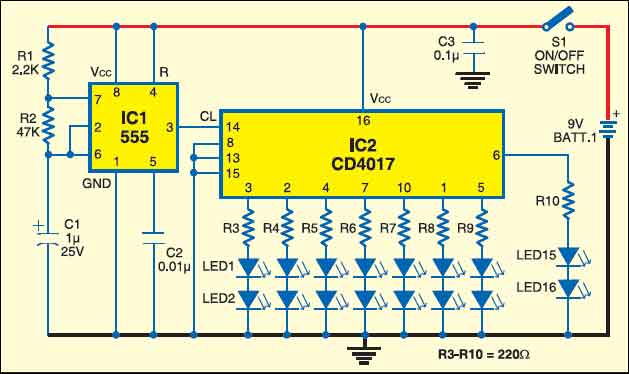
The rim flasher is a simple sequential circuit built around timer IC 555 (IC1) and decade counter IC CD4017 (IC2) as shown in Fig. 1. IC1 is wired as an astable multivibrator whose output is fed to clock pin 14 of decade counter IC2. All the eight outputs of IC2 are connected with two LEDs each. These 16 LEDs (LED1 through LED16) are arranged round the rim of a flying-saucer-like toy. The colour of LEDs used may be yellow, pink orange or even white to give a good colour effect.
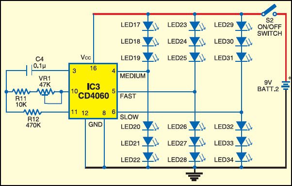
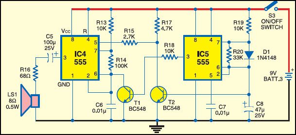
The dome flasher circuit is built around a 14-stage ripple-carry binary counter and oscillator IC CD4060 (IC3) as shown in Fig. 2. Three outputs are used here. Three groups of LEDs with six LEDs in each are arranged such that each group flashes at a different rate. Preset VR1 (47-kilo-ohm) is used to vary the flash cycle. discharge cycle of capacitor C8 (47µF) generates a sawtooth waveform which rises rapidly but falls slowly. This waveform is fed to the base of transistor T2 (BC327), which is an emitter follower. Its output is used to control frequency modulation. It is fed to pin 5 of timer IC4. The rectangular-wave output at pin 3 of timer IC5 is fed to transistor BC548 (T1) to operate timer IC4, which is also an asymmetrical multivibrator. If a 75-ohm-impedance speaker is available, there is no need to use resistor R16 (68 ohms).

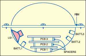
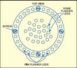
For assembling the circuit, use two deep, plastic bowls of about 20 cm diameter each. Make sure that bowls have rims to facilitate fixing of LEDs with small screws. For fixing the LEDs, refer to Fig. 4. Assemble the rim flasher, dome flasher and sound generator circuits on separate general-purpose PCBs and mount these on the deep bowls along with batteries and speaker. PCB1, PCB2 and PCB3 are for rim flasher, dome flasher and sound generator, respectively.
The assembled flying saucer is shown in Fig. 5. When you switch on the circuit, rim LEDs and dome LEDs flash, and at the same time, a sound is generated. This gives the simulated effect of an unidentified flying object.