


 Here is a signal lamp for safe highway driving. The lamp automatically emits brilliant tricolour light when a vehicle approaches the rear side of your vehicle. It emits light for 30 seconds that turns off when the approaching vehicle overtakes. The ultra-bright blue, white and red LEDs of the signal lamp emit very bright light to alert the approaching vehicle’s driver even during the day, giving additional safety during night, or when you need to stop your vehicle on side of the highway. The circuit saves considerable battery power.
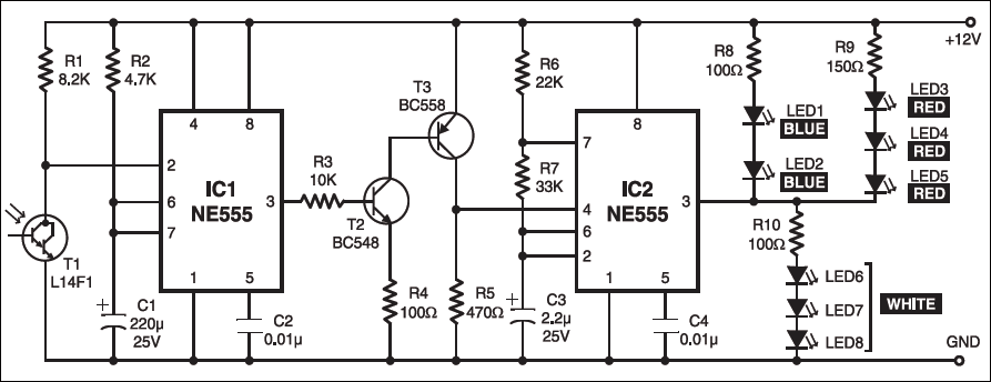
The circuit is built around two timer ICs NE555 (IC1 and IC2). IC1 is designed as a standard monostable, while IC2 is designed as an astable. Darlington phototransistor L14F1 (T1) is used as a photosensor to activate the monostable. The collector of phototransistor T1 is connected to trigger pin 2 of IC1, which is normally kept high by resistor R1.
When headlight from an approaching vehicle illuminates the phototransistor, it conducts to give a short pulse to IC1, and the output of IC1 goes high for a period determined by resistor R2 and capacitor C1. The output of IC1 is fed to the base of transistor T2 via resistor R3. Transistor T2 conducts to drive transistor T3 and its collector goes high to take reset pin 4 of IC2 to high level. This activates astable IC2, which switches on and off the LED chain alternately. The intermittent flashing of LEDs gives a beautiful tricolour flashlight effect.

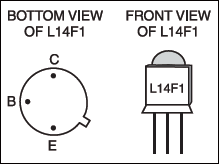
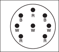
The circuit can be easily constructed on a small piece of general-purpose PCB. Fig. 2 shows the bottom and front views of Darlington phototransistor L14F1. The proposed arrangement of LEDs, which are soldered in a circular fashion on a general-purpose PCB, is shown in Fig. 3. Use a circular reflector for the LEDs to get brighter light. Fix the LED arrangement on the rear side of your vehicle, and the phototransistor where it is illuminated directly by the headlight of the approaching vehicle. 12V DC supply to the circuit, can be provided by your vehicle battery with proper polarity.

disadvantages of this circuit?
Hai
sir
pls help to get more details on this topic including; uses;
demerit and merit..
Order of the components is done here or no?
Please send us the cost of the circuit?