 Infrared (IR) illuminators are widely used to improve the image-capturing quality of security cameras fitted in dark zones. Just like our eyes, cameras also can’t record movements in dark. However, unlike our eyes, most of the latest cameras can capture infrared light.
In an IR Illuminator, many infrared IR LEDs are grouped together to throw good amount of IR light. Typically, LEDs output at 470 nm (blue region), 525 nm (green region) and 625 nm (red region). IR LEDs produce longer wavelengths, 880 nm and 940 nm being the common ones. Most CCD cameras are a little more sensitive to 880 nm, although when these LEDs are used for security applications, some individuals can detect a very dim red glow from them. The 940nm LED radiations are completely invisible to the eye. Some of these LEDs are clear, while others are tinted with pale shades of dark gray, blue or even black.
They come in various configurations and radiation patterns, but 5mm types with 15- to 40-degree patterns are the most popular.
Typically, IR LEDs run at around 1.3 to 1.7 volts, depending on the LED current (typically 10 to 30 mA). However, this may vary with the type and manufacturer. Practically, IR illuminators may have 6 or 60 to 100 or more LEDs, depending on the output needed.
Infrared illuminator circuit
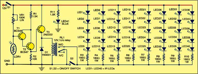
The circuit (refer Fig. 1) can be divided into three parts: ambient light sensor, relay driver and IR LEDs. The ambient light sensor is built around multiturn linear potmeter VR1 and light-dependent resistor LDR1. The relay driver section is built around transistors T1 through T3. The IR LEDs section is built around LED1 through LED40.

The light sensor circuit is a simple transistor switch with the base of the Darlington pair (formed by T1 and T2) connected to a voltage divider. Variable resistor VR1 and the 10mm encapsulated LDR are used to sense the ambient light. As light falls on the surface of LDR1, its resistance changes. The amount of minimum light needed to actuate the relay through driver transistor T3 can be varied by adjusting VR1. Diode 1N4001 eliminates any back voltage when the relay e-energises. Switch S1 is the mains power on/off switch and switch S2 is added to bypass the ambient light detection function.
Relay RL1 energises only when the ambient light level falls below a threshold value set by VR1, i.e., when it’s dark. Normally-opened (N/O) contacts of the relay ground path to the IR LEDs (LED1 through LED40) to make them glow. The blue LED (LED41) indicates the circuit activity. When there is ambient light and you want to use the illuminator, switch S2 ‘on.’ All the LEDs (LED1 through LED40) glow to fulfil your requirement.
Construction & testing
Assemble the circuit on a general-purpose PCB and enclose in a suitable cabinet. The IR LEDs assembly is very important. A set of 40 (5X8) 5mm infrared LEDs (IR LED1 through IR LED40) with independent current-limiting resistors (R3 through R10) per string is used. This section is powered by the input DC supply through the relay contacts.
Mount IR LEDs on the general-purpose PCB board such that these make three circles. After soldering, carefully cut the outside of the circuit board in a round shape and fit it in a suitable metal/plastic cabinet. If available, add a suitable reflector sheet for the IR LED bank. Finally,fit the LDR bank on top of the enclosure with switches, indicator-sensitivity-control pot and power input socket. Fig. 2 shows the infrared illuminator unit.
To make the circuit actuate the relay when the intensity of ambient light is less than the preset light level, throw light on LDR1 and then slowly adjust the potentiometer until LED1 lights up and the relay energises.
The article was first published in December 2010 and has recently been updated.


