


 Today, most of the electronics devices come with a liquid crystal display (LCD). Even new fridges have it. It is interesting as well as useful to know how to use LCDs with any device. Here is how to interface a graphics LCD module with a microcontroller.
Graphics LCD module
There are various types of graphics LCD modules available in the market depending on pixel size such as 120×64, 128×128, 240×64 and 240×128. The graphics LCD used here has a pixel size of 240×128 and is based on T6963 controller IC. The module type is SS24E12DLNW-E from UTC.

The 240×128 LCD panel screen has 240 horizontally and 128 vertically arranged pixels. It can be used for graphics or for text in any combination, like one area of 240×64 for graphics and another area of 240×64 for text. Also, the entire area of 240×128 can be used either for graphics or text.
The LCD module gets the data or command instructions from the interfaced microcontroller through data lines D0 through D7. Depending upon the command received, the T6963 finds out the data from the internal VRAM and displays it as graphics or text at appropriate place on the screen. The module has a 128-character internal character-generator ROM (CG-ROM) and can control up to 64 kB of external video RAM (VRAM). A number of character attribute functions are also available.

For communication from/ to the connected CPU, the LCD module has eight data lines (D0 through D7), write and read lines, chip-enable line, and a command or data line.
Resetting the module. As soon as the power is switched on, the T6963 IC must first be hardware reset by pulling the reset pin down for at least one millisecond.
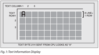
Font selection. Font size of the LCD module, like 6×8 (which occupies six horizontal pixels and eight vertical pixels) or 8×8 (which occupies eight horizontal pixels and eight vertical pixels), is selected by pulling the FS pin high or low, respectively. Thus if a 6×8 font is selected, you can get 240/6=40 columns and 128/8=16 text display rows. If an 8×8 font is selected, you can get 240/8=30 columns and 128/8=16 text display rows.
The text information is sent by the microcontroller byte by byte to the LCD module. The first byte is displayed in the left corner on the top as shown in Fig. 1. The second byte is displayed to the right of the first byte and so on. The last byte is the 30th byte in the row. The 31st byte is displayed in the second row.
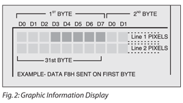
The graphics image is also sent by the microcontroller byte by byte to the LCD module. If a bit is set as ‘1’ it will be displayed in dark, and a ‘0’ bit will be displayed as a clear pixel. The first byte is displayed in the left corner on the top as shown in Fig. 2. The second byte is displayed to the right of the first byte and so on. The last byte is the 30th byte in the line. Thus the 31st byte is displayed in the second line of pixels.
Initialisation of the LCD module
The initialisation process is always done at the beginning of the software program before we start displaying anything on the screen. It is done by sending a series of commands through data lines from the microcontroller to the LCD module. Some commands may need extra information and therefore should be sent with corresponding data bytes. The C/D pin of the LCD module must be pulled high when sending the command, and pulled low when sending the data.
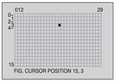
Cursor pointer set. The ‘cursor pointer set’ command has two data bytes associated with it to specify the position for the cursor. This is the only command which will shift or move the cursor. The cursor cannot be shifted automatically by the data-write commands. Cursor position should be set within the actual display area.
