


 Using this IR transmitter/receiver & music generator circuit, audio musical notes can be generated and heard up to a distance of 10 metres. The circuit can be divided into two parts: IR music transmitter and receiver. The IR music transmitter works off a 9V battery, while the IR music receiver works off regulated 9V to 12V. Fig. 1 shows the circuit of the IR music transmitter.
IR transmitter
It uses popular melody generator IC UM66 (IC1) that can continuously generate musical tones. The output of IC1 is fed to the IR driver stage (built across the transistors T1 and T2) to get the maximum range.
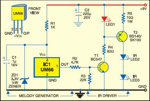
Here the red LED (LED1) flickers according to the musical tones generated by UM66 IC, indicating modulation. IR LED2 and LED3 are infrared transmitting LEDs. For maximum sound transmission these should be oriented towards IR phototransistor L14F1 (T3).

IR music receiver
The IR music receiver uses popular op-amp IC µA741 and audio-frequency amplifier IC LM386 along with phototransistor L14F1 and some discrete components (Fig. 2).
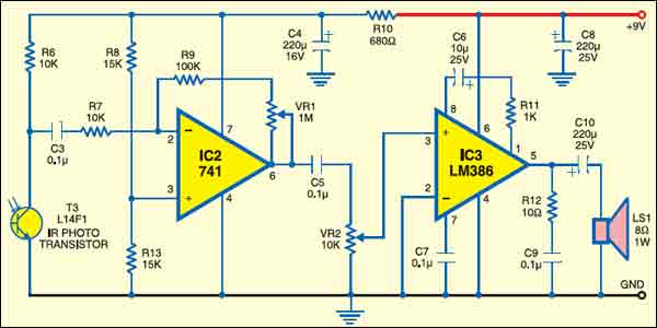
The melody generated by IC UM66 is transmitted through IR LEDs, received by phototransistor T3 and fed to pin 2 of IC µA741 (IC2). Its gain can be varied using potmeter VR1. The output of IC µA741 is fed to IC LM386 (IC3) via capacitor C5 and potmeter VR2. The melody produced is heard through the receiver’s loudspeaker. Potmeter VR2 is used to control the volume of loudspeaker LS1 (8-ohm, 1W). Switching off the power supply stops melody generation.

The article was first published in January 2009 and has recently been updated.

How to write this project in resume
All the details are present within the article.