


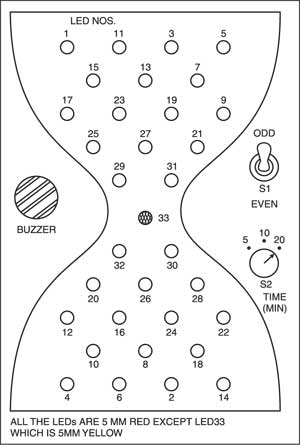
This circuit (Fig. 1) simulates the old hourglass timer. A total of 32 LEDs create the effect of sand grains passing from the upper half of sand-glass to its lower half.
LED hourglass timer circuit
When the power is switched ‘on’, shift registers IC3 and IC4 are reset by the power-on-reset circuit formed by resistor R34 and capacitor C7. After a few seconds, the sand-glass action starts. IC CD4060B (IC2) is a 14-stage ripple binary counter with built-in oscillator. It generates clock pulses, which are fed to both the shift registers (IC3 and IC4). The clock frequency can be adjusted by preset VR1, while rotary switch S2 helps in selecting time periods.
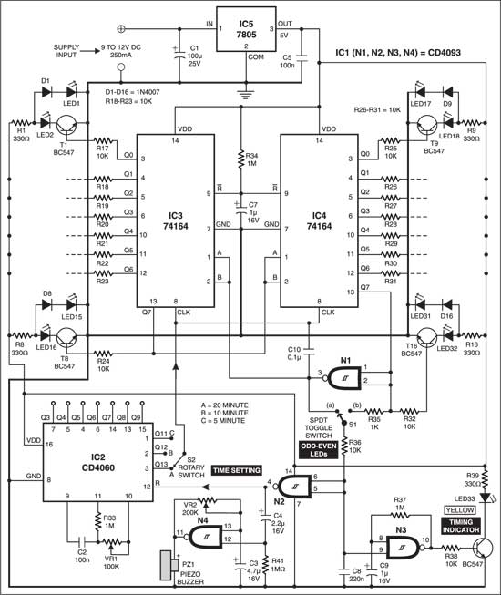
Time period options of 5, 10, and 20 minutes have been provided. Additional options are available on utilising outputs Q3 through Q9 of IC2.

Switch S1 is an SPDT switch, which selects odd- or even-numbered set of LEDs. In other words, it selects which side of the sand-glass is up.
Circuit operation
Assuming S1 to be in position (a), every clock pulse causes shifting of a high logic level to IC3 via its inputs A and B, as long as pin 13 (Q7) of IC4 remains low. The MSB (Q7) of IC3 is shifted to inputs A and B of IC4. Controlled by the outputs of shift registers, transistors T1 through T16 switch off the odd-numbered LEDs and switch on the even-numbered LEDs in sequence, when pin 13 of IC4 goes high. Counter IC2 is reset via gates N1 and N2 of IC1 (CD4093, which is a quad 2-input Schmidt NAND gate), while oscillator N4 sounds piezobuzzer PZ1. When one timing cycle is completed, the buzzer stops after giving two beeps and the timing indicator yellow LED also stops blinking. The tone of buzzer can be set by VR2 and C3.

Now reverse the sand-glass and flip SPDT switch S1 to (b). Logic low levels are shifted to IC3, with pin 13 of IC4 being at logic high. Now, even-numbered LEDs go off one by one, and odd-numbered LEDs light one by one until pin 13 of IC4 goes low and the buzzer beeps. LED33 indicates that the sand-glass is ready for timing.
Take a 15x5cm piece of dark-coloured acrylic or plastic sheet to mount LEDs. Mount switch S1 at the back of the cabinet. The circuit works off a 9V, 250mA supply provided by a battery eliminator. Take care while wiring LEDs. The circuit is symmetrical and it can be assembled on a veroboard or a general-purpose PCB.
The article was first published in February 2003 and has been recently updated.

please reply with a embedded c program for it