


This light sensitive fire alarm circuit is extremely sensitive, low-cost and easy to assemble  even by a beginner. It uses infrared photo transistor as fire sensor.
Light sensitive fire alarm circuit and working
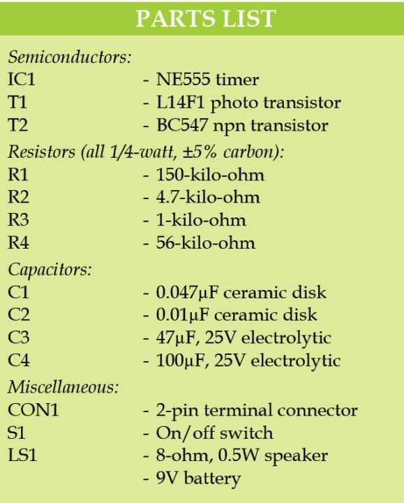
Circuit diagram of the light sensitive fire alarm is shown in Fig. 1. It is built around L14F1 photo transistor (T1), BC547 transistor (T2) and NE555 timer (IC1).

T1 can sense both infrared and visible light. NE555 based a stable multi vibrator is used for audible warning. Resistors R3 and R4 and capacitor C1 decide the frequency. Here, frequency is around 272Hz, which can be changed by changing values of R3, R4 or C1.

 When T1 senses light, T2 stops conducting. As a result, reset pin 4 of IC1 is held high. This makes the multivibrator to function and an alarm to sound in loudspeaker LS1.
Construction and testing
An actual size, single side PCB of the light sensitive fire alarm is shown in Fig. 2 and its component layout in Fig. 3. After assembling the circuit on a PCB, enclose it in a suitable plastic case.


Download the PCB and component layout PDFs: click here
Make a small hole in the plastic case for the photo transistor (L14F1) so that fire flame is detected/sensed easily through it. T1 sensor should not face directly towards normal light sources like sunlight, bulbs or tubelights to avoid a false alarm.
The circuit works off a 9V battery.
Pradeep G. is B.Sc. (Physics) and a regular contributor to international magazines. He is also a small-business owner in south India

i need a electrical project to do
For reference: click here
Wat r the advantages of this alarm over conventional one??