 Functional generators and logic analyzers both are important tools for all electronics engineers and most of the time we wish they should be so small that we can carry them any were and the also so today we will such a tool that can work as a logic analyzer and function generator as well and is so small that you can carry in a pocket. Here we will design 4 channel logic analyzer and combine it with a separate functional generator. So let’s start our design with a collection of the following components,
Bill Of Materials

Coding
Logic Analyser
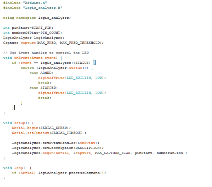
First we need to make the code so our ESP 8266 act as logic analyzer here we can make 4 GPIO of ESP into LOgic analyzer so you can say we are going to make 4 channel logic analyzer using which we can see the input signal so first, we need to prepare the Arduino IDE and install ESP 32 and ESP 8266 board to Arduino IDE for that you can refer to the official ESP website after installing the ESP boards to Arduino IDE we are now ready to program, Now download the logic analyzer library and add it to Arduino IDE using library manager or you can simply extract the zip file of the library in the library folder of Arduino and the library automatically get added.
https://sigrok.org/wiki/Openbench_Logic_Sniffer#Short_Commands
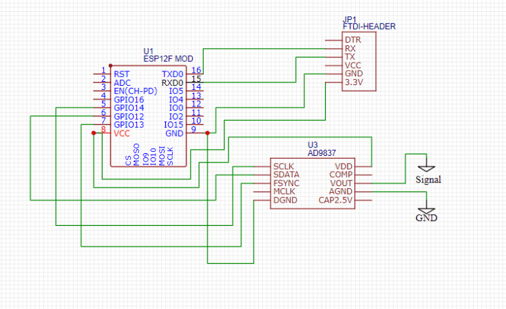
Now we can do coding here in code we can set the frequency and sample number and then select the right port and board ie ESP 8266 12. And connect the ESP RX TX pins to FTDO TX RX pins and VCC to ESP 12 F 3.3 V pin of FTDI and GND to GND and then GPIO 0 to GND and upload the code to ESP 12 F.
Functional Generator
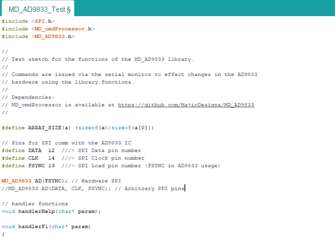
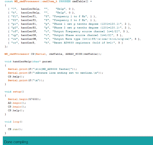
Now we need to create the code for the function generator here we go to sketch and then open library manager and search AD9833 and then install the library for the functional generator now we can create the code in the first part of the code we need to set the SPI pin numbers in code for connection with our AD 9833 functional generator and then the other functions in code select the right board and pot number and upload the code like we do in previous ESP8266 board . Now our device is ready.
Connection
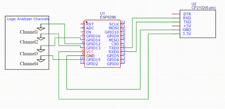
Now connect both esp with components as in circuit diagram where one ESP act as logic analyzer and other act as functional generator combine both exp and put in single enclosure and now our Logic analyse and functional generator is ready .
Testing
Now our logic analyzer is ready, but our device can capture the logic data using GPIO pins, which act as a channel for the logic analyzer, but we can’t view it without any software, so if you have a PC or laptop, then install the Sigrok using the following link.
https://sigrok.org/wiki/Main_Page
Now open the Sigrok Pulseview and then go to connect and select the Open Bench logic snipper. Now, select the serial port and baud rate and then scan for the device. After scanning, you will receive the name of the logic analyzer device. The name used for this device is the ESP board. It shows ARDUINO ESP with 4 channels. Select it, and now your 4-channel logic analyzer is ready. Now you can connect the input of the logic analyze channel ie pin 12 13 14 15 of ESP to see the signals to read the details of the signal you can refer to the following link.
https://sigrok.org/wiki/Openbench_Logic_Sniffer#Short_Commands
For the functional generator plug FTDI for the functional generator and then open the serial port in Arduino and now send “?” to the device in return it shows you commands you do now select the wave type you want to generate and the frequency of wave and now your wave is generated and the output can be received at the out pins of the functional generator as in circuit diagram.


