


Most of the IR remotes work reliably within a range of 5 metres. The circuit complexity increases if you design a long range IR transmitter for reliable operation over a longer range, say, 10 metres. To double the range from 5 metres to 10 metres, you need to increase the transmitted power four times.
If you wish to realise a highly directional IR beam (very narrow beam), you can suitably use an IR laser pointer as the IR signal source. The laser pointer is readily available in the market. However, with a very narrow beam from the laser pointer, you have to take extra care, lest a small jerk to the gadget may change the beam orientation and cause loss of contact.
Long range IR transmitter
Here is a simple circuit that will give you a pretty long range. It uses three infrared transmitting LEDs (IR1 through IR3) in series to increase the radiated power. Further, to increase the directivity and so also the power density, you may assemble the IR LEDs inside the reflector of a torch.

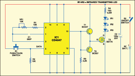
For increasing the circuit efficiency, a MOSFET (BS170) has been used, which acts as a switch and thus reduces the power loss that would result if a transistor were used. To avoid any dip during its ‘on’/‘off’ operations, a 100μF reservoir capacitor C2 is used across the battery supply. Its advantage will be more obvious when the IR transmitter is powered by ordinary batteries. Capacitor C2 supplies extra charge during ‘switching on’ operations.
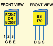
As the MOSFET exhibits large capacitance across gate-source terminals, a special drive arrangement has been made using npn-pnp Darling ton pair of BC547 and BC557 (as emitter followers), to avoid distortion of the gate drive input. Data (CMOS-compatible) to be transmitted is used for modulating the 38 kHz frequency generated by CD4047 (IC1). However, in the circuit shown here, tactile switch S1 has been used for modulating and transmitting the IR signal.

Assemble the circuit on a general- purpose PCB. Use switch S2 for power ‘on’/‘off’ control. Commercially available IR receiver modules (e.g., TSOP1738) could be used for efficient reception of the transmitted IR signals.
Applications for IR Transmitter:
- IT Transmitter can be used in Infrared remote controlling applications such as AC or TV Remote controls, some smartphones, etc.
- IR Transmitters can be used for security applications
The article was originally published in January 2007 and was recently updated.

Comment: please, where can it be applied because I don’t see any receiver circuit as well
You can use any 38KHz Infrared Receiver IR Receiver module like TSOP1738, TSOP1838, etc.