


[stextbox id=”grey” caption=”Test code with 7406 (invert with 7407):”]000000 Vout=Vmax (unadjustable)
000001 Vout=1.25V (VR1)
000010 Vout=3V (VR2)
000100 Vout=5V (VR3)
001000 Vout=7.5V (VR4)
010000 Vout=9V (VR5)
100000 Vout=12V (VR6)[/stextbox]
The maximum output voltage on CON3 and CON4 is with code 111111 on the outputs of IC3 and depends on the input voltage of IC2. Please note that, if you use 7407, the codes will be non-inverted, and if you use 7406, the codes will be inverted.
The 6-bit input digital code D0 through D5 is buffered with 7406 or similar (IC3). With an open collector, the IC works as a translator/buffer between standard TTL levels to higher voltages needed for LM317.

Download the PCB and Componet Layout PDFs: Click Here
If the requirement of current is more than 1A, then select adjustable regulator IC2 from series LM317T (1.5A), LM350 (3A) or any compatible adjustable-linear regulator.

This makes the DAC adaptable to a lot of applications. In many cases, there is no need to start the output voltage from 0V. This makes the solution even simpler.
Input digital code D0 through D5 is buffered with IC3, which should be obligatory with open connector. The preferred device is 7406 or better, with outputs that can work with up to 30V.
Power requirements are from a common configuration built around step-down transformer X1 (secondary voltage 18V to 20V with current 1A or above), bridge rectifier BR1 and voltage regulator IC 7805 (IC1). The mains power is applied on connector CON1. 5V is available at connector CON5.
The selection of mains transformer X1, bridge rectifier and heat sinks for IC1 and IC2 depends on the required maximum output current from the DAC. IC1 and IC2 can be mounted on a common heat-sink after proper mounting is done.
The load is connected to connector CON3. A DC voltmeter with 50V range is connected at CON4 for measuring the output voltage. The DAC can be tested with 12V/5W/0.4A light bulb, 12V/0.3A fan, heating element for thermostat with nominal current up to 0.3A and maximum current below 1A and similar loads.
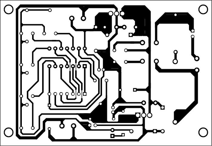
Construction and testing
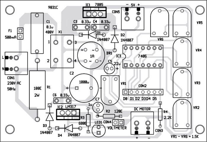
An actual-size, single-side PCB layout for the low-cost 6-bit DAC is shown in Fig. 2 and its component layout in Fig. 3.
Petre Tzv Petrov was a researcher and assistant professor at Technical University of Sofia, Bulgaria, and expert-lecturer at OFPPT, Casablanca, Kingdom of Morocco. He is currently working as an electronics engineer in the private sector in Bulgaria
