 This article presents a low-noise power supply with four 78L15 voltage regulators in parallel, giving about 15V DC output. The modern environment has become noisier, and every power supply is a powerful source of electrical noise, which is highly undesirable for high-quality audio and test equipment.
If you need a power supply of +15V with a tolerance of ±10 per cent and noise lower than 10µVrms, then 78L15 voltage regulators can be used. It is because they are low-cost, easily available, have output current of 100mA or more, low output voltage tolerance, small MO package (TO-92), internal current limiting, and thermal protection.
Most 78L15 ICs have an output current of 40mA, but we may need a current of 160-250mA. The use of M series, such as 78M15 regulators with 0.5A, is not suitable because this would require complex filter circuits to minimise noisy output voltages. Also, these regulators are available in TO-220 packages, which are more difficult to mount as compared to TO-92 packages.
One of the solutions to get higher current output is to use 78L15 voltage regulator ICs in parallel. An advantage of this configuration is that if one of the parallel regulators fails, the remaining regulators will provide output voltage and current. But note that 78LXX regulators have large output noise, sometimes more than 100µVrms in the range of 10Hz to 100kHz.
Generally, the noise produced by the voltage regulators is random. So, the averaging method—a noise reduction technique—can be applied to reduce the noise and tolerance of the output voltage. Ideally, we should apply this method over an infinite number of voltage sources, but it also works over a small number of voltage regulators. Here we will see a solution based on this method.
Circuit and working
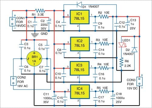
Circuit diagram of the low-noise power supply with four 78L15 voltage regulators in parallel is shown in Fig. 1. It is built around bridge regulator BR1, four 78L15 voltage regulators (IC1 through IC4), 1N4007 diodes (D1 and D2), LED1, and a few other components.
The circuit uses 18V AC input or 18V DC inputs with RC filters to reduce noise. The RC filters for 18V DC input comprise of resistor R1 and capacitors C1, C2, and C11. The 18V AC input comprises rectifier bridge BR1 and capacitors C1, C2, C3, C5, C6, C7, and C11. The effectiveness of the noise filtering depends on the internal resistance of the AC voltage source and diodes in the bridge.

The circuit has four 78L15 voltage regulators in parallel. Each of the regulators has an equalisation resistor (R2 through R5) at the output. The values of the equalisation resistors are equal to or greater than 10 ohms. The resistors are much higher in value than the internal output resistance of the regulators.
If required, you may add a capacitor of 0.1µF to each regulator (refer capacitors C4, C9, C8, C14, C10, C16, C15, and C17 in the circuit). These individual capacitors guarantee stable operation of the voltage regulators and reduce high-frequency noise to some extent.
Selection of equalisation resistors and RC filters. The output voltage of the circuit depends on the load current and equalisation resistors. A higher equalisation resistor will produce better equalisation and better filtering of the noise. But it will also lead to a higher dependency on the output voltage from the load current. That is, larger resistors will improve the filtration of the noise from the regulators but will affect load regulation. In this application, noise reduction is more important. The usual values of these resistors are from 10 to 30 ohms.
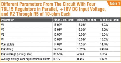
The main parameters with 10-ohm resistors R2 through R5 are given in Table 1.

The cut-off frequency of the output filter built around the equalisation resistors and output capacitors C12, C13, and C18 should preferably be below 20Hz when we use 50Hz/60Hz AC mains input. With resistor R= 10-ohm and capacitor C=1000µF, we have frequency F(-3dB)=15.9Hz along with some harmonic suppression in the 50/60Hz AC mains present in the circuit after rectification.
Construction and testing
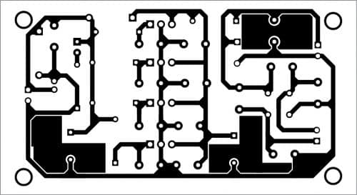
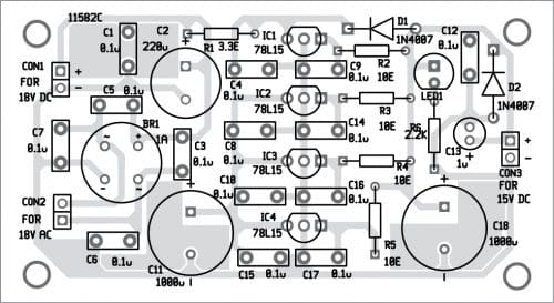
An actual-size PCB layout for the low-noise power supply is shown in Fig. 2 and its components layout in Fig. 3. After assembling the circuit on the PCB, connect either 18V DC across CON1 or 18V AC across CON2 as input and take 15V DC output across CON3.


Download PCB and component layout PDFs: click here
This article presents a low noise power supply with four 78L15 voltage regulators in parallel that produces output of 14.4V at 0.25A. The average output current per regulator is below 75mA, which is below the defined 100mA output current for the 78L15 series. (We have an average current of 62.5mA per the regulator, given a total of 4×62.5mA=250mA).
The circuit has a current limiting function and short-circuit protection. It does not need any adjustment to work properly.
Preferably, we should use a 78L15 regulator with a tolerance of ±4% or better and equalisation resistors with maximal practical values. Here, we are not concerned about output regulation but are interested in the low-noise output and equal output current distribution between voltage regulators connected in parallel.
Petre Tzv Petrov was a researcher and assistant professor at the Technical University of Sofia, Bulgaria, and an expert lecturer in OFPPT (Casablanca), Kingdom of Morocco. Now he is working as an electronics engineer in the private sector in Bulgaria.


Please specify the same for higher current application ( more than 10 A).
i had to add 1u caps on the adj pin to get the voltaqe more than 8v then it finally hit 15v. problem was that with a 1k load it dropped to 14.69 volts. i also had to increase the polarized caps to smooth out the ripple on the 18v continuous output.
The circuit as it is working fine. But if there is noise in your power supply source, you need to add capacitor to smoothen it at the output.
out put ampare application ( more than 10 A
You can use regulator like LM196/LM396 in parallel combination to get more than 10A output. However, design can be bulky and noise may be compromised.