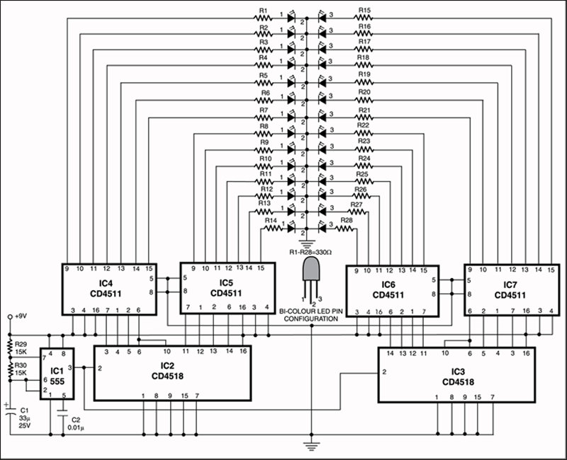
The circuit as shown in the figure employs 14 bi-colour (red and green) LEDs having three terminals each. Different dancing colour patterns are produced using this circuit since each LED can produce three different colours. The middle terminal (pin 2) of the LEDs is the common cathode pin which is grounded. When a positive voltage is applied to pin 1, it emits red light. Similarly, when positive voltage is applied to pin 3. it emits green light. And when positive voltage is simultaneously applied to its pins 1 and 3, it emits amber light. The circuit can be used for decorative lights.

IC1 (555) is used in astable mode to generate clock signal for IC2 and IC3 (CD4518) which are dual BCD counters. Both counters of each of these ICs have been cascaded to obtain 8 outputs from each. The outputs from IC2 and IC3 are connected to IC4 through IC7 which are BCD to 7-segment latch/decodor/driver ICs. Thus we obtain a total of 14 segment outputs from each of the IC pairs consisting of IC4 plus IC5 and IC6 plus IC7. While outputs from former pair are connected to pin No. 1 of all the 14 bi-colour LEDs via current limiting resistors, the ouputs of the latter pair are similarly connected to pin No.3 of all the bi-colour LEDs to get a magical dancing lights effect.


