


 A global positioning system (GPS) receiver is used to get precise geographical location by receiving information from satellites. It not only gives information about location but also information like time, date, height and speed. It is so useful that most smartphones are embedded with it.
GPS receivers have many applications in aircraft, ships, sea vessels and the like for navigation purposes. Smartphones with maps (like Google Maps) find routes to a specific destination such as a restaurant, hospital or hotel. With the help of a GPS, a target camp can be located and a missile launched to destroy it.
The GPS receiver module includes an antenna and a built-in processor. The built-in processor calculates the required information from the signals’ output serially in form of strings using NMEA (expanded as National Marine Electronics Association) 0183 protocol. These strings are received serially by the host computer for display or by host processor/controller to take any decision or action.

NEMA protocol includes standard messages given by the GPS receiver. Some standard message outputs from NMEA are GGA, ZDA, VTC, RMC, GSA and GSV. The string starts with $GPRMC tag and gives time, latitude, longitude, etc.

The project here demonstrates how to get location (latitude and longitude), time, date, speed and course-angle information using a GPS receiver. It uses 8-bit AVR microcontroller (MCU) ATmega16A (ATMega32 was used by the author) to get data from the GPS receiver and display it on an LCD. All this information is combined in a single string that starts with $GPRMC tag.
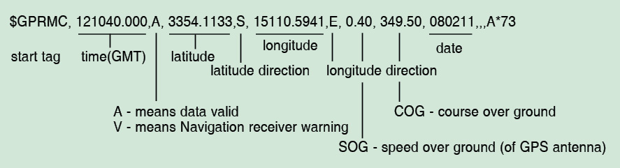
RMC stands for Recommended Minimum GNSS data. GPRMC string format is explained below, and shown in Fig. 2.
GPRMC string format
The complete string is of 65 to 70 characters including start tag. The time, that is, Greenwich Mean Time (GMT) or Coordinated Universal Time (UTC) immediately follows start tag. It can be in 1ms, 10ms or 100ms resolution. Then there is location information that includes latitude and longitude with direction.
Next is the speed of the GPS antenna, which is given in knots. Course angle is the angle of the GPS antenna with respect to true North in counter-clockwise direction. The date is given at the end. It is also with respect to GMT/UTC.
Download PCB and component layout PDFs: click here
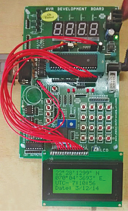
Therefore in this single string we get all the information. The AVR MCU extracts this string from GPS output and further extracts all required details and displays these on the LCD in proper format. Author’s prototype is shown in Fig. 1. GPS receiver used for this prototype is a marine GPS receiver MR-600 and a sunrom GPS receiver (1216) with an active antenna.
Circuit and working
As shown in Fig. 3, the circuit is built with AVR MCU ATmega16A (IC1), RS232-level converter chip MAX232 (IC2) and a 16×4 LCD panel (LCD1). The GPS module has three terminals for interfacing, namely, Tx, Rx and Gnd. It gives a series of strings as serial output, which is connected to RS232-level side-input pin R2IN (pin 8). Output is taken from TTL-level side-output pin R2OUT (pin 9), which is given to serial receive pin RXD (pin 14) of IC1.
Operation of the circuit depends on the GPS receiver module. IC1 receives a series of strings from the GPS module and extracts the required string from a bunch of ten strings in real-time. Out of these, it extracts the string that starts with $GPRMC. It simply discards all others.
From the extracted string, it extracts all necessary information like time, date, latitude, longitude, speed and course angle. At last it displays all extracted details on the LCD panel.
Download source code: click here
Software
Functionalities of the AVR MCU are due to the program embedded into its internal flash memory. The software program is written in C language using AVR studio software. It is compiled using GCC compiler available with AVR studio. When the program is compiled successfully, it generates a hex file, which is loaded into ATmega16A using AVR SPI programmer.
C program is made up of 12 different functions described as follows:
LCD_sendcmd sends an 8-bit command (character) to the LCD to initialise or configure it.
LCD_senddata sends 8-bit data (character) to the LCD, which is displayed on the screen.
LCD_write_string displays the complete string (message) on the LCD.
LCD_init initialises the LCD in 8-bit mode, 8×5 dots/character USART handling function.
usart_init initialises built-in USART and set baud rate to 9600 bps.
usart_getch returns one character (8-bit data) received from the serial port.
display_latitude displays the received latitude on the LCD in degree-minute-second format.
display_longitude displays the received longitude on the LCD in degree-minute-second format.
display_date displays the date (as per GMT) on the LCD in dd/mm/yy format.
display_time displays Indian Standard Time (IST) on the LCD in hh:mm:ss format.
display_speed displays GPS antenna speed in knots with 1-digit precision after decimal point as xxx.x knots.
display_course displays the GPS antenna angle with respect to true North in counter-clockwise direction.
Construction and testing
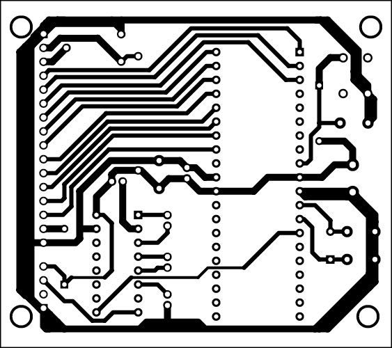
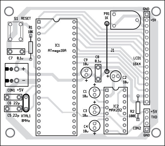
An actual-size, single-side PCB for the GPS receiver is shown in Fig. 4 and its component layout in Fig. 5.
Note. The system displays the received string from GPS directly on the LCD. It does not manipulate the GPS parameters. So all parameters given by the GPS receiver are directly displayed on the LCD screen. To check the validity of values, check the validity of the received signal (using hyper terminal).
If you are looking for the difference between Microprocessor and Microcontroller, you can read it here.
This article is a part of the Top 15+ Microcontroller Projects. If you want to read more projects based on Microcontroller, can go through this article.
Ashutosh M. Bhatt is M.Tech in embedded systems. Currently, he is a lecturer of electronics and radio engineering at government polytechnic, Jamnagar, Gujarat

is there any coding needed for this project.if it need then please send it to my mail id :[email protected]
hey have you guys got anything in return on mail related to code?
hello
plz. can you show step by step to get GPS information with avr?
can you send it on email [email protected]
is there any coding needed for this project.if it need then please send it to my mail id : [email protected]