Morse code is a method of transmitting textual information as a series of on-off tones, lights or clicks that can be directly understood by a trained listener without using any special equipment. The International Morse Code encodes alphabets, numerals and a small set of punctuation and procedural signals as standardised sequences of short and long signals called ‘dots’ and ‘dashes,’ respectively.
Each character (letter or numeral) is represented by a unique sequence of dots and dashes. The duration of a dash is three-times the duration of a dot. Each dot or dash is followed by a short silence, equal to the dot-duration. The dot-duration is the basic unit of time measurement in code transmission. Morse code speed is measured in words per minute (wpm). Characters have differing lengths as these contain differing numbers of dots and dashes. Consequently, words also have different lengths depending on the total number of dots and dashes, even if these contain the same number of characters.
The Morse code encoder presented here converts texts, numbers and special characters into Morse code as audible output on a piezobuzzer (PZ1). The encoder along with any Morse code transmitter can be used for transmission of Morse code.
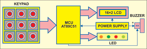
Fig. 1 shows the block diagram of the Morse code encoder. The Morse code message is entered through a keypad made of tactile switches S2 through S9 (Fig. 2). The message appears on the LCD for visual checking. LEDs indicate the applied command. The transmitted Morse code message is played on a piezobuzzer and indicated by the glowing of LED4.

Circuit Description for Morse Code Encoder
Fig. 2 shows the circuit of the microcontroller-based Morse code encoder. It comprises microcontroller AT89C51 (IC1), regulator 7805 (IC2), and LCD display and a few discrete components. Microcontoller AT89C51 is the heart of the circuit. It is an 8-bit microcontroller with 4kB Flash programmable and erasable read-only memory (PEROM), 128 bytes of RAM, 32 input/output lines, two 16-bit timers/counters, a five-vector two-level interrupt architecture, a full-duplex serial port, on-chip oscillator and clock circuitry.
Port pins P1.0 through P1.7 of the microcontroller are connected to switches S2 through S9 that are used for inputting the various commands. These port pins are pulled up with 10-kilo-ohm resistor network RNW1. Data pins D0 through D7 of the LCD are connected to port pins P2.0 through P2.7 of the microcontroller. The control pins—register select (RS), read /write (R/W) and enable E—are connected to port pins P0.0, P0.1 and P0.2, respectively. Preset VR1 is connected to pin 3 of the LCD for contrast control.
LED2 through LED5 are connected to pins P0.3 through P0.6 to provide the visual indication for ‘EDIT,’ ‘TRANSMIT,’ ‘MORSE OPTICAL’ and ‘DONE’ mode, respectively. Port pin P0.7 of the microcontroller drives the piezobuzzer with the help of transistor T1.
When the buzzer is kept in front of the microphone of a Morse code transmitter, text entered on the display gets transmitted. The Morse code receiver receives the transmitted code and decodes it to retrieve the message. Power-on reset is provided by the combination of resistor R2 and capacitor C3. Switch S1 is used for manual reset. A 12MHz crystal along with two 33pF capacitors provides the basic clock frequency.
To derive the power supply for the circuit, the 230V AC mains is stepped down by transformer X1 to deliver a secondary output of 9V, 500mA. The transformer output is rectified by a full-wave rectifier comprising diodes D1 through D4. The full-wave rectified output is smoothened by capacitor C1 and regulated by voltage regulator IC 7805 (IC2). Capacitor C2 bypasses the ripples present in the regulated supply. LED1 acts as a power indicator. Resistor R1 limits the current through the LED1.
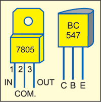
Fig. 3 shows pin details of voltage regulator IC 7805 and transistor BC547.
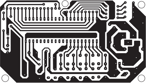
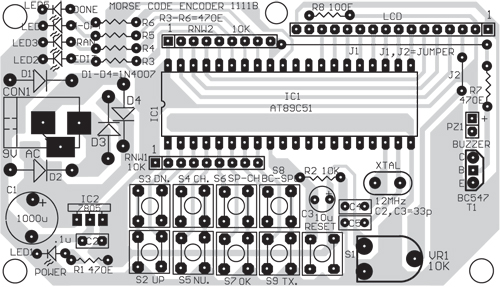
Assemble the circuit on a PCB to minimise time and assembly errors. An actual-size, single-side PCB for the microcontroller-based Morse code encoder is shown in Fig. 4 and its component layout in Fig. 5.
Operation
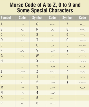
The table shows Morse code of uppercase letters A through Z, numbers 0 through 9 and some special characters.
Power-on the circuit and press switch S1 to reset it. Let’s say you want to transmit the message ‘HELLO.’ This message consists of alphabets, so press key S4 (CH.) to input capital letters from A to Z. Select letters from A to Z by pressing key S2 (UP) for forward movement of the alphabets and key S3 (DN.) for reverse movement of the alphabets. Once the desired alphabet is selected, confirm the selection by pressing ‘OK’ (S7) key. In a similar way, other letters of the message can be encoded. Every time you select a letter, it is confirmed by pressing S7 (OK) key.
Download Source Code: click here
The message can consist of letters, numbers and special characters. For inputting numbers, press switch S5 (NU.). Select the desired number by using key S2 or S3. Confirm the selection by pressing S7 (OK) key.
For inputting special characters (only nine special characters have been programmed in this encoder), press key S6 (SP.- CH.). Select the desired special character by using either key S2 or S3. Confirm the selected special character by pressing key S7 (OK). Every time key S7 is pressed, the cursor moves forward by one digit. To move the cursor backward by one digit, press key S8 (BC._SPC.). After the entire message is encoded, it can be heard as an audible tone from piezobuzzer PZ1 by pressing transmit key S9 (TX).
Edit mode is indicated by LED2, while transmit mode is indicated by LED3. After the desired message is transmitted, LED5 glows momentarily to indicate that transmission of the desired message is complete. LED4 glows for 500 milliseconds when a ‘dot’ is transmitted and for 1500 milliseconds when a ‘dash’ is transmitted.
Software
The software for the microcontroller-based Morse code encoder is written in ‘C’ language and compiled using the Keil µVision4 compiler. The pro-gram is well-commented and easy-to-understand. Burn the generated hex code into the microcontroller by using a suitable programmer.
If you are looking for the difference between Microprocessor and Microcontroller, you can read it here.
This article is a part of the Top 15+ Microcontroller Projects. If you want to read more projects based on Microcontroller, can go through this article.
V. Nagaraj is an assistant professor and head of department of Electronics, Govt Arts College, Dharmapuri, while K.N. Sreekumar is an assistant professor at ECS department, R.V.S. College of Arts & Science, Coimbatore.


Sir,what is the Programmer you used to dump.. hex file into the micro controller
which software is used to dump a program into microcontroller?