


The basic requirements of a realtime programmable timer generally used in schools and colleges for sounding the bell on time are:
• Precise time base for time keeping.
• Read/write memory for storing the bell timings.
• LCD or LED display for displaying real time as well as other data to make the instrument user-friendly.
• Keys for data entry.
• Electromechanical relay to operate the bell.
We are describing here a sophisticated, yet economical, school timer based on Motorola’s 20-pin MC68HC705J1A microcontroller.
[stextbox id=”info” caption=”Main features of MC68HC705J1A”]• 14 bidirectional input/output (I/O) lines. (All the bi-directional port pins are programmable as inputs or outputs.)
• 10 mA sink capability on four I/O pins (PA0-PA3).
• 1,240 bytes of OTPROM, including eight bytes for user vectors.
• 64 bytes of user RAM.
• Memory-mapped I/O registers.
• Fully static operation with no minimum clock speed.
• Power-saving stop, halt, wait, and data-retention modes.
• Illegal address reset.
• A wide supply voltage range from-0.3 to 7 volts.
• Up to 4.0 MHz internal operating frequency at 5 volts.
• 15-stage multifunction timer, consisting of an 8-bit timer with 7-bit pre-scaler.
• On-chip oscillator connections for crystal, ceramic resonator, and external clock.[/stextbox]
Description
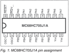 The pin assignments and main features of the microcontroller are shown in Fig. 1 and the Box, respectively. The complete system is divided into four sections, namely, the time keeping section, the input section (keyboard), the output (display, indicators, and relay driving) section, and power supply and battery backup.
The time-keeping section. Accurate time-keeping depends on the accuracy of time base used for driving the microcontroller. In this project, the microcontroller is driven by AT-cut parallel resonant crystal oscillator that is expected to provide a very stable clock. A 3.2768MHz crystal provides a time base to the controller.
The frequency (fosc) of the oscillator is internally divided by 2 to get the operating frequency (fop). This high-frequency clock source is used to control the sequencing of CPU instructions.
Timer. The basic function of a timer is the measurement or generation of time-dependant events. Timers usually measure time relative to the internal clock of the microcontroller. The MC68HC705J1A has a 15-stage ripple counter preceeded by a pre-scaler that divides the internal clock signal by 4. This provides the timing references for timer functions.
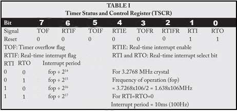 The programmable timer status and control register (TSCR) is used for deciding the interrupt rate. It can be programmed to give interrupts after every 16,384, 3,2768, 65,536, or 131,072 clock cycles. In Table I, the control word is set to provide the interrupts after every 16,384 cycles. For a 32,768MHz crystal, the interrupt period will be 10ms. Thus, timer interrupts will be generated after every 10 ms (100 Hz). That is, 100 interrupts will make 1 second.
Now time-keeping becomes very simple. As we are having a precise 1-second time count, a real-time clock can be easily built.
The MC68HC705J1A has a 64 byte RAM that is used for data storage, Real time (in terms of seconds, minutes, hours, days of a month, and months) is stored in this RAM. Thus an accurate real-time clock is generated.
The input section. For setting the real-time clock and storing operating times, the timer requires to be programmed externally. Data is fed using the keyboard.
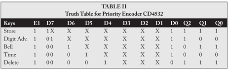 Press-to-on type keys are interfaced to the microcontroller using an 8-bit priority encoder CD 4532. This encoder detects the key-press operation and generates the equivalent 3-bit binary data. Its truth table is shown in Table II. The priority encoder is interfaced to port A of the microcontroller.
Various keys used in the timer, along with their functions, are described below:
Time (4): For setting real time in minutes and hours.
Bell (5): For setting the bell’s operating timings.
Digit Advance (6): Data setting is done digitwise (hour’s digit followed by minute’s digit). The Digit Advance key shifts the decimal point to the right.
Store (7): For storing the data (real time or bell time).
Delete (3): For deleting a particular bell timing.
Here, the figures within parentheses indicate the decimal equivalents of 3-bit binary data from the keyboard.
Set and run modes. Data setting is possible only in set mode. Set mode or run mode can be selected by toggle switch S6. By using a lock switch for S6, the timer can be protected from unauthorized data entry/storage.

sir please give source code