


Cellphone chargers can be a major challenge while traveling, as power sources are not always easily accessible. If you keep your cellphone continuously on, its battery will likely drain within five to six hours, rendering the phone unusable.
Having a fully charged battery becomes especially crucial when you’re far from the nearest relay station.
Here’s a straightforward solution: a portable cellphone charger that can recharge your battery within just two to three hours.

Table of Contents
Cellphone Charger Circuit

Basically, the cellphone charger is a current limited voltage source. Generally, cellphone battery packs require 3.6-6V DC and 180-200mA current for charging. These usually contain three NiCd cells, each having 1.2V rating. Current of 100mA is sufficient for charging the cellphone battery at a slow rate.
A 12V battery containing eight pen cells gives sufficient current (1.8A) to charge the battery connected across the output terminals. The circuit also monitors the voltage level of the battery. It automatically cuts off the charging process when its output terminal voltage increases above the predetermined voltage level.
DIY Mobile Charger – Operation and Working
Timer IC NE555 is used to charge and monitor the voltage level in the battery. Control voltage pin 5 of IC1 is provided with a reference voltage of 5.6V by zener diode ZD1. Threshold pin 6 is supplied with a voltage set by VR1 and trigger pin 2 is supplied with a voltage set by VR2.
When the discharged cellphone battery is connected to the circuit, the voltage given to trigger pin 2 of IC1 is below 1/3Vcc and hence the flip-flop in the IC is switched on to take output pin 3 high. When the battery is fully charged, the output terminal voltage increases the voltage at pin 2 of IC1 above the trigger point threshold.
This switches off the flip-flop and the output goes low to terminate the charging process. Threshold pin 6 of IC1 is referenced at 2/3Vcc set by VR1. Transistor T1 is used to enhance the charging current. Value of R3 is critical in providing the required current for charging. With the given value of 39-ohm the charging current is around 180 mA.
Construction and Testing
The circuit can be constructed on a small general-purpose PCB. For calibration of cut-off voltage level, use a variable DC power source. Connect the output terminals of the circuit to the variable power supply set at 7V.
Adjust VR1 in the middle position and slowly adjust VR2 until LED1 goes off, indicating low output. LED1 should turn on when the voltage of the variable power supply reduces below 5V. Enclose the circuit in a small plastic case and use suitable connector for connecting to the cellphone battery.
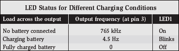
Note: At EFY lab, the circuit was tested with a Motorola make cellphone battery rated at 3.6V, 320 mAH. In place of 5.6V zener, a 3.3V zener diode was used. The charging current measured was about 200 mA. The status of LED1 is shown in the table.

What is the design values for a 9v battery charging circuit ?
What are the values of resistances and capacitor for charging a 9v battery ?
What are the calculations needed to find the values one would need for various battery ratings?
Homany hours getting ?
Kindly elaborate your query.
what happen to the pin 7 of NE555?
Here, pin 7 of NE555 is not used in this application