Presented here is a multi-tone configurable alarm that can be activated by temperature and other physical parameters. Its output tone can be selected through different switch combinations. Such an alarm is highly desirable when multiple alarms are present in the same area. Different tones can be selected for different alarms so that you can easily know which alarm has triggered. The alarm in this circuit is activated by temperature.
Circuit and working
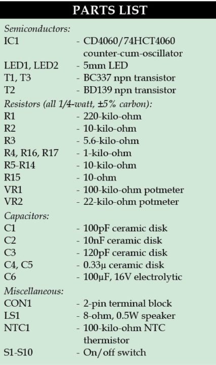
 CD4060 (IC1) is a CMOS integrated circuit that contains an oscillator and a 14-stage ripple counter/divider. It has three oscillator terminals (1, 0 and 0), ten buffered outputs of the counter (Q4-Q10 and Q12-Q14) and an active ‘high’ master reset. It is used in this project to produce ten different square waves at the same time. These square waves can be mixed to produce different output tones using switches (S1-S10).
The oscillator frequency mainly depends on the value of components C3, R2, R1 and VR1. If needed, oscillator frequency can be trimmed using potmeter VR1. Trimming is useful to obtain different clock frequencies when several alarms are in use near each other. If trimming is not needed, VR1 can be replaced with a fixed-value resistor.

With increasing temperature, resistance of thermistor NTC1 decreases and the biasing voltage for transistor T3 increases. Once it reaches beyond the threshold established with VR2, transistor T3 conducts and reset pin 12 of IC1 goes ‘low.’
 The make of NTC1 is not critical but VR2 should have an appropriate value depending on the selected NTC. The counter in IC1 starts advancing with rise in temperature and square-wave signals start appearing on the outputs. Through push-to-on switches S1-S10 you may select the frequencies required in the audio alarm signal. The produced composite signal available at the base of transistor T1 is amplified to drive loudspeaker LS1. The mixed multi-tone signal produced is generally difficult to ignore.
Though 5V power supply is recommended here, the circuit works with 2V to 6V. Also, CD4060 may be replaced with 74HCT4060 or 74HC4060 for IC1. LED1 indicates the presence of power supply, and resistor R16 is for current limiting.
Construction and testing
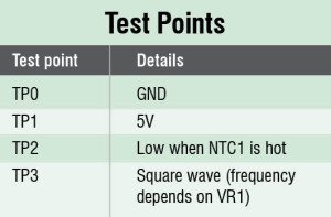
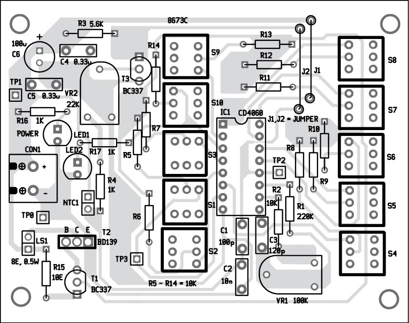
An actual-size, single-side PCB for the alarm is shown in Fig. 2 and its component layout in Fig. 3. After assembling the circuit on a PCB, enclose it in a suitable plastic case. Fix 2-pin terminal block connector CON1 on the PCB for power supply. Connect NTC1 through external wires for temperature sensing. fix potmeters VR1 and VR2 on the front panel for frequency control and threshold level settings.


Download PCB and component layout PDFs: click here
The author was a researcher and assistant professor at the Technical University of Sofia (Bulgaria) and an expert-lecturer in Kingdom of Morocco. Now he is working as an electronics engineer in the private sector in Bulgaria.


