 The temperature of some electronic components used in a device may rise unexpectedly and these might get damaged. This multichannel visual thermometer can indicate the problem through glowing LEDs. Since transistors are very cheap and widely available, this circuit uses these as low-cost temperature sensors and amplifiers.

Circuit and working
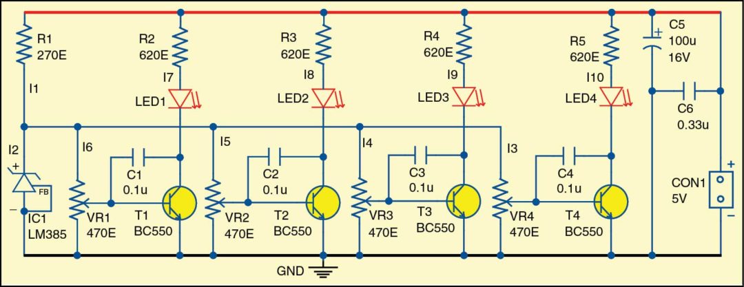
 The multichannel visual thermometer (Fig. 1) is built around IC LM385 (IC1) and transistors BC550 (T1 through T4) and a few other components. The circuit is based on the fact that voltage across the forward polarised emitter-base junction of the bipolar transistors is reduced with around 2.2mV/°C. IC1 produces a reference voltage of around 1.2V.
The transistors can work as temperature sensors and amplifiers-cum-comparators at the same time. These should be mounted with very good thermal contact over the monitored components (transistors, heat-sinks, diodes, transformers, power cables, heating elements, etc).
Adjustment of the circuit is simple. At room temperature (say, around 25°C), adjust potmeters in such a way that there is no visible light from the LEDs.
When you heat sensors T1 through T4, LEDs (LED1 through LED4) should start emitting light in proportion to the temperature of the corresponding transistors.
For testing, you can heat (usually below 150°C) the transistors for a short time with a soldering iron. You can adjust different thresholds depending on the temperature of interest, with the LEDs emitting light. The 5V DC power supply is connected across CON1.


Download PCB and Component Layout PDFs: click here
LM385 has a maximal current of 20mA, which should be taken into consideration when values of R1 and VR1 through VR4 are calculated. Current I2 (see Fig. 1) should always be between 10µA and 20mA. Currents I3 to I6 should be at least ten times higher than the required maximal base current for transistors T1 through T4. Currents I7 through I10 should be minimal for producing light in LEDs at temperatures of interest, for example, between 5mA and 10mA. Capacitors C1 through C4 prevent oscillation from transistors and may be omitted.
Construction and testing
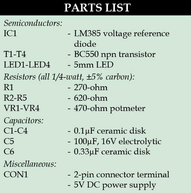
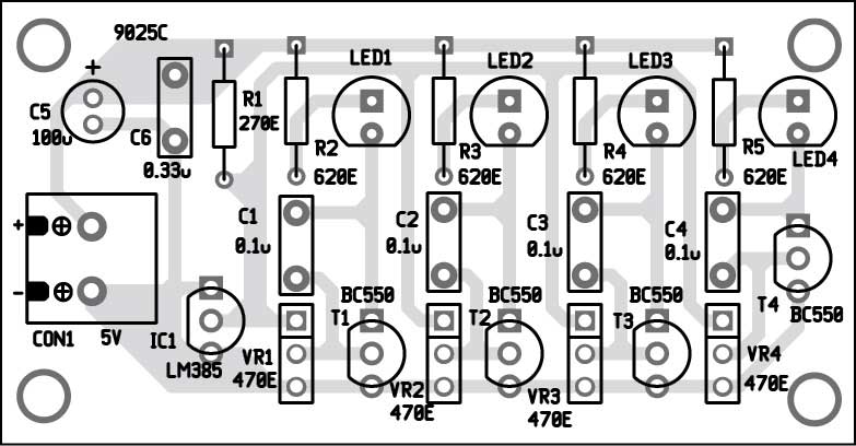
An actual-size, single-side PCB for the visual thermometer is shown in Fig. 2 and its component layout in Fig. 3. Enclose the PCB in a suitable small box in such a way that transistors T1 through T4 absorb the heat when installed in a suitable instrument. Conductors between the transistors and the PCB should be as short as possible, and no longer than 50cm.
For more exciting projects: click here
Petre Tzv. Petrov was a researcher and assistant professor in Technical University of Sofia, Bulgaria, and expert-lecturer in OFPPT, Casablanca, Kingdom of Morocco. Now he is working as an electronics engineer in the private sector in Bulgaria


please how do i get a picture of the circuit?
on a bread board please
Kindly elaborate your query please.
Just right click on the image and save picture as>>save in downloads
i can’t find the ic lm385 any other substitute?
if i can a video of how it is connected i will be very grateful
thanks… do i keep it close to a heat sink or install a heat sink on it