


 This music operated lighting effect generator comprises five sets of 60W bulbs that are arranged in zig-zag fashion. The bulb sets glow one after another depending on the intensity of the audio signal. No electrical connection is to be made between the music system and the lighting effect generator circuit. You just need to place this musical light chaser gadget near the speakers of the music system.
Musical Light Chaser Circuit
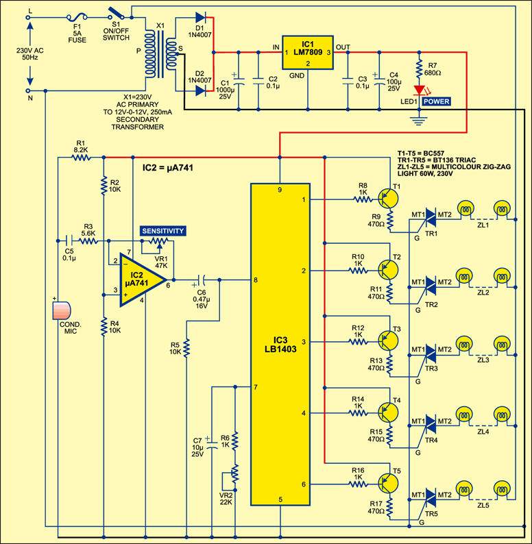
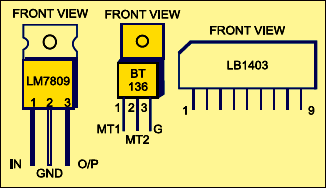
Fig. 1 shows the complete circuit of the musical light chaser, while Fig. 2 shows pin configurations of 9V regulator 7809, triac BT136 and level meter IC LB1403. The circuit is powered by regulated 9V DC. The AC mains is stepped down by transformer X1 to deliver a secondary output of 12V AC at 250 mA. The transformer output is rectified by a full-wave rectifier comprising diodes D1 and D2 and filtered by capacitors C1 and C2. Regulator IC 7809 (IC1) provides regulated 9V power supply to the circuit. Closing switch S1 provides power to the circuit and LED1 glows to indicate that the circuit is ready to work.
Circuit operation
When you put your music system in front of the condenser microphone of the light chaser, the sound pressure variation is converted into electrical signals by the condenser microphone. These weak electrical signals are amplified by op-amp µA741 (IC2), which is configured as an inverting amplifier. Using preset VR1 you can set the sensitivity of the circuit. The amplified output is fed to IC LB1403 (IC3) at its input pin 8. IC3 is a five-dot LED level meter commonly used in stereo systems for LED bargraph displays. It has a built-in amplifier, comparators and constant current source at its output pins.

Depending on the intensity of the input audio signals, all or some outputs of IC3 go low to drive transistors T1 through T5, which, in turn, fire the corresponding triacs TR1 through TR5 via their gates and multicoloured zig-zag bulb sets comprising ZL1 through ZL5 glow. When the audio level is low, only triac T1 is fired and the zig-zag bulb set ZL1 turns on and off sequentially. When the audio level is high, triacs TR1 through TR5 get fired and all the bulb sets (ZL1 through ZL5) turn on and off sequentially.
Pin 7 of IC3 is used for selecting the response speed of the lighting. The larger the time constant, the slower the response, and vice versa. The time constant can be changed by changing the values of resistor R6, variable resistor VR2 and capacitor C7. Here, variable resistor VR2 is used for varying the response speed of the chaser light as desired. When VR2 is set in the minimum resistance position, the response is very fast, and when it is set at the maximum resistance, the response is slow.

Construction & testing
The complete circuit including the power supply can be constructed on any general-purpose PCB or a small Veroboard. Triacs TR1 through TR5 should be kept away from the op-amp and its related components. The metallic parts of the triacs should not touch each other and the other parts of the circuit. After assembling the circuit, house it in a suitable shockproof plastic cabinet. Make some holes in the cabinet for heat dissipation.
Note
- Some zig-zag lights have a special bulb called ‘master bulb’ for automatic flickering. It should be removed and replaced with a simple non-flickering colour bulb.
- Never touch any naked part of the circuit when it is connected to the mains.
The article was first published in January 2005 and has recently been updated.
