


 Here is a mains-operated door-bell that produces parrot-like sweet voice without requiring any musical IC. The circuit is cheap and easy to construct. The AC mains is fed to the circuit without using any step-down transformer.
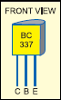
The complete circuit is shown in Fig. 1. The main components of the circuit are a resistor-capacitor network, transistor BC337 and audio output transformer X1. The oscillation frequency depends on the combination of resistors R4 and R5 and capacitors C3, C4 and C5. When switch S1 is closed, the audio signal generated due to oscillations is amplified by transistor BC337 and parrot-like sound is reproduced from loudspeaker LS1 connected across the secondary of transformer X1.
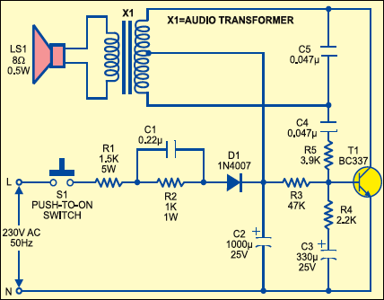
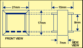
Here we have used an 8-ohm, 0.5W loudspeaker. The audio output transformer (X1) is normally used in transistor radio. The function of the audio output transformer is to transform the high impedance of the output amplifier to match the much lower impedance of the speaker. This is necessary to get an efficient transfer of the audio signal to the speaker. If a wrong audio transformer is used, the result can be low output and loss of tone quality. The audio frequency tone across the speaker terminal is about 3 kHz. The dimensions of the audio transformer used in the experimental setup are shown in Fig. 2.

The circuit is powered directly from 220V AC mains. The operating DC voltage obtained at the cathode of diode D1 is about 6V. However, if you press switch S1 continuously for a few seconds, the maximum voltage developed at this point may go up to 20 volts, which must be avoided to prolong the life of the circuit. R1 limits surge current in the circuit. The parallel combination of resistor R1 and capacitor C1 limits the circuit current to a safe level for circuit operation. R2 across C1 provides DC path for the current as well as a discharge path when the circuit is switched off. This is to prevent a possible shock to the operator by charged capacitor C1.

after opening found charing smell. cap after diode and transistor BC 158 getting hot. resistance centre tap to collector 34.5 and other side 31.5 ohms
. replaced cap,transistor but fail. small cap are also replaced. diode and resistances are OK. secondary side of transformer is OK. what should I do now? is it the transformer??? probably internally short circuit between turns!
pl help.
.