

Instruction set for ATmega8535
The instruction set comprises several arithmetic, logical, branch and bit-test type instructions. You can download a 150-page user manual for the AVR instruction set from Atmel’s site‘www.atmel.com/dyn/resources/prod_documents/doc0856.pdf.’ A summary of the instruction set is given on pages 299 through 301 of the Atmega8535(L) datasheet.
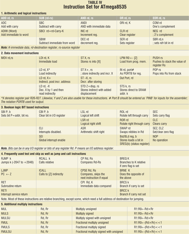
Some of the important instructions are given in Table IV.

Points to be noted

1. When the relative call or jump instruction is executed, the entire memory address space can be accessed.
2. During interrupts and subroutine calls, the return address value is stored in the stack space, which is to be defined by the user at the beginning of every program in SRAM space.
3. The 16-bit stack pointer is read-/write-accessible in the I/O space.
4. The 512-byte data RAM is easily accessed through five different addressing modes supported.
5. A flexible interrupt module has its control registers in the I/O space with an additional global interrupt enable bit in the status register. Every interrupt has a separate address for vectoring, where the instruction causing it to jump to the memory area of that particular interrupt has to be kept stored by the programmer.
There are many interrupts available in ATmega8535. In order to use any interrupt, you need to place the address of the program of the respective interrupt service routine at the vector address.
From location ‘001H’ to ‘014H, ’there are 20 such interrupt vector locations in the order of their priority. Address ‘000H’ is used for the reset vector. A reset may be caused by power-on reset, brownout reset and watchdog reset, or externally by making pin 9 low. Table 19 on page 45 of the datasheet lists the details of reset and interrupt vectors.
Note that here we are dealing with word addresses, so each location is actually two bytes long. In this twobyte location, if you place a RETI (return from interrupt) instruction, nothing will be done upon that interrupt. For example, if you place a jump instruction to the required routine, you can write:
rjmp timer_routine
Then you can use that interrupt to jump to the timer_routine.
As mentioned above, the interrupt vectors follow the reset address at ‘000H,’ wherein a jump instruction to the corresponding actual memory addresses, defined by the labels, is placed. For example, the instruction:
RJMP Int0
It means that the external interrupt routine has the label ‘Int0,’ to which the processor jumps upon pin 17 getting a high logic signal. Also, at the label ‘Int0,’ if a simple return instruction is entered as:
Int0: reti
This instruction simply ignores such an interrupt and returns to the main program. In case you need to process the interrupt, enter the necessary code starting at label ‘Int0.’