


 Presented here is a Windows-based equipment controller project that can control up to eight electrical devices using a personal computer. Connecting a computer to external devices is becoming essential in our day-to-day life for automation. But to communicate to a device we need a common communication protocol such as a serial COM port, USB or wireless connectivity. Here we have used the serial communication protocol to control the devices.
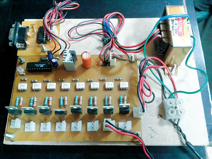
 Many modern personal computers have no serial COM ports but these are still found in industrial machines or scientific instruments. This project was inspired by the construction project, ‘Multiple Device Switching Through PC’s Parallel Port’ published in May 2008 issue of EFY. Parallel ports are not in use any more, nor are they available on PCs and laptops. So we have designed this project for the serial port, which is still being used for communication in some PCs. The author’s prototype is shown in Fig. 1.
Circuit and working of the equipment controller
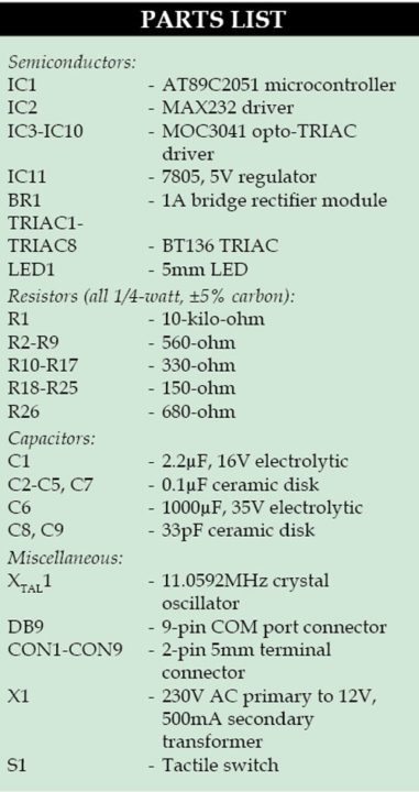
The circuit diagram is shown in Fig. 2. It consists of microcontroller AT89C2051 (IC1), MAX232 driver (IC2), eight opto-TRIAC drivers MOC3041 (IC3 through IC10), eight BT136 TRIACs (TRIAC1 through TRIAC8), a DB9 serial COM port connector, a 5V voltage regulator (IC11) and a few other common components.
Power supply. The 230V, 50Hz AC mains is stepped down by transformer X1 to deliver a secondary output of 12 V, 500mA. The transformer output is rectified by full-wave rectifier module BR1, filtered by capacitor C6 and regulated by IC 7805 (IC11). Capacitor C7 bypasses the ripples present in regulated supply. The regulated 5V is used to power the microcontroller, MAX232 driver, MOC3041 opto-TRIAC drivers and BT136 TRIACs. LED1 indicates presence of power supply.
Microcontroller. The AT89C2051 is a low-voltage, high-performance CMOS 8-bit microcontroller with 2k bytes of Flash programmable and erasable read-only memory. The device is manufactured using Atmel’s high-density non-volatile memory and is compatible with the industry-standard MCS-51 instruction set. It has 128 bytes of RAM, 15 I/O lines, two 16-bit timer/counters, a five-vector two-level interrupt architecture, a full duplex serial port, a precision analogue comparator, an on-chip oscillator and clock circuitry. an 11.0592MHz crystal is used as the external clock source. You may use two 33pF capacitors along with the crystal to get proper oscillation frequency.

Please share full source code..
Dear swanand, the source code is present on third page of the article.
can you please share vb code for the GUI application
You can download the complete source code including the VB code from here. http://www.efymag.com/admin/issuepdf/PC%20Based%20Electrical%20Equipment%20Control.rar
Hello sir,
How much time will it require to complete the whole working setup?
There is only Hex file available. Can you provide complete code of the micro controller?
where is the circuit diagram?
Dear Deepak Agarwal, the circuit diagram is present on the second page.
If you have to put a MicroController in the circuit to control 8 outputs from a PC, why not use Arduino? It can be interfaced with a PC with USB (Unlike this circuit which uses Serial port which is hard to find in PC today). No need to make circuit board because everything is on Arduino board.
Technology keeps on changing and so is serial com port. This article was published a few years back. But the fact is that you can find Serial Port in some Desktop PCs, server PCs, industrial PCs, etc. and if not PCI slots are available in them for adding Serial port cards.
hello sir,
i noticed that in pcb layout device 1 and and remaing 2to 8 device connected in different manner with traic but in circuit diagram they all are conected in same way
i think devic 1con is not correctly conected in pcb layout plzz tell me the layout is correct or not
thanks reply asap.
Thanks for pointing out the mistake! There is a wrong track connecting to TRIAC1 and DEVICE1. It has been corrected now. The corrected actual-size PCB layout is available in PDF format for download. To download it, you can click ‘Click here’ hyperlink given just below the PCB layout in this article.
How can I get all setup Including PCBs