 Here is a temperature logging system based on PIC16F887 microcontroller (MCU), Wi-Fi and ThingSpeak application programming interface (API). ThingSpeak is an open source Internet of Things project (IoT). This application and API to store and retrieve data from things over the Internet. It enables you to collect, store, analyse, visualise and act on the data received from sensors or electronic circuits.
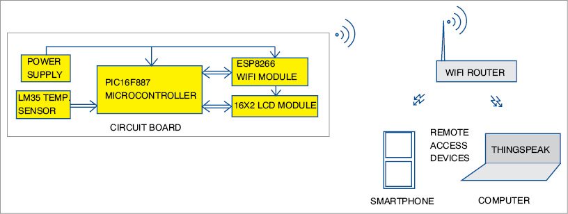
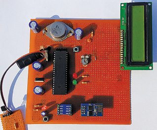
Block diagram of the temperature-logging system is shown in Fig. 1. Author’s prototype is shown in Fig. 2. Temperature data transmitted from the circuit board can be accessed on a smartphone or PC through Wi-Fi using ThingSpeak API.
Circuit and working
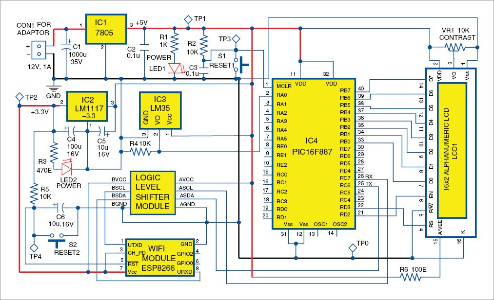
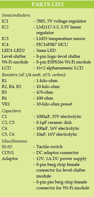
Circuit diagram of the IoT Wi-Fi temperature-logging system is shown in Fig. 3. It is built around PIC16F887 MCU (IC4), ESP8266 Wi-Fi module, logic-level shifter, LM35 temperature sensor (IC3), 3.3V regulator LM1117-3.3 (IC2), 5V regulator 7805 (IC1) and 16×2 LCD module (LCD1).
PIC16F887 MCU
This is a high-performance RISC CPU, 8-bit CMOS MCU, and has 8192-word flash memory, 368 bytes SRAM, 256 bytes EEPROM and 35 I/Os. It supports up to 20MHz oscillator/clock input and has a wide operating voltage range of 2.0V-5.5V. Its inbuilt A/D converter has a 10-bit resolution and three internal timers. It supports enhanced USART module, in-circuit serial programming (ICSP), 3-wire SPI and I2C.
ESP8266 Wi-Fi module
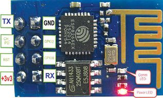
ESP8266 Wi-Fi module (Fig. 4) is a self-contained system on chip (SoC) with an integrated TCP/IP protocol stack that can give any MCU access to your Wi-Fi network. ESP8266 is capable of either hosting an application or offloading all Wi-Fi networking functions from another application processor.
Each ESP8266 module comes pre-programmed with an AT command set firmware. This means that you can simply hook this up to your Arduino device and get about as much Wi-Fi ability as a Wi-Fi shield can offer (and that is just out of the box). ESP8266 module is an extremely cost-effective board with a huge and an ever-growing community.
 This module requires a 3.3V DC regulated supply. Power consumption of the ESP module is around 250mA when transmitting. You need proper power supply. Do not power it directly from a 5V supply source. It also needs a level shifting/conversion to protect the 3.3V device from 5V.
Logic-level shifter
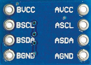
ESP8266 module is not capable of converting 5V to 3.3V. We used an external logic shifter/converter as shown in Fig. 5. +3.3V, CH_PD and RST pins are kept at 3.3V for normal functioning of ESP8266. Logic-level converter is a device that safely steps down 5V signal to 3.3V.
LM35 temperature sensor
The LM35 series is of precision integrated circuit temperature sensors, whose output voltage is linearly proportional to Celsius (Centigrade) temperature. LM35 is rated to operate over -55°C to +150°C, while LM35C is rated for a -40°C to a +110°C temperature range. This sensor has a linear scale factor of 10mV/°C and operates from 4V to 30V.
Power supply
Power supply section includes a 5V regulator 7805 (IC1) and a 3.3V regulator LM1117-3.3 (IC2). The MCU, logic-level shifter and LCD are powered by 5V and ESP Wi-Fi module by 3.3V supply. Voltage for ESP8266 for all its pins is 3.3V. If you are using an adjustable voltage regulator, carefully set proper voltage to 3.3V.
In this project, temperature data from LM35 sensor is fed to pin 2 of PIC16F887 MCU. This data is given to ESP8266 Wi-Fi module through a logic-level shifter. Temperature data transmitted from the Wi-Fi module can be accessed on a remote device like a smartphone or laptop using ThingSpeak’s website.
ESP8266 Wi-Fi module has two GPIO pins that can be used for connecting to the Internet through an MCU using specific firmware. However, these are not used in this project and it works on the default firmware.
ESP8266 Wi-Fi module is used here to connect to your Wi-Fi modem and upload temperature data to ThingSpeak. You can view that data from a smartphone or laptop in the form of a plotted-line graph.
In this project, an LCD is also used as a user interface device to see circuit configuration status and temperature data. Data lines (D0 through D7) of the LCD are connected to port B of IC4.
Software
espIOT code for PIC16F887 MCU is written in C language. It is compiled using MPLAB IDE version 8.91 and HI-TECH C compiler version 9.83.0.10920. The generated hex code is burnt into the MCU chip using MPLAB ICD 2 programmer board.
Download PCB and component layout PDFs: click here
Download source code: click here
Construction and testing
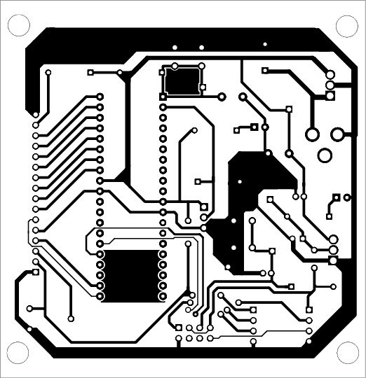
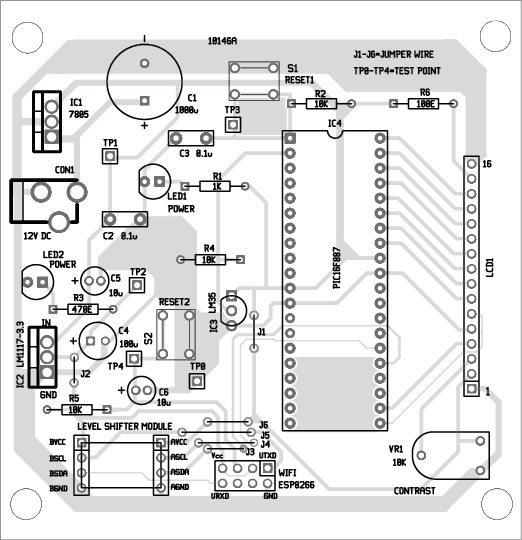
An actual-size, single-side PCB layout of the Wi-Fi temperature logger is shown in Fig. 6. and its component layout in Fig. 7. When the circuit is switched on, the program initialises the LCD and flashes welcome message ‘ESP Temp Logger’ on the LCD.
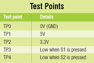
If there is any display problem on the LCD, check voltages at various points as listed in the test point table. If the LCD is showing a proper message, go to www.thingspeak.com
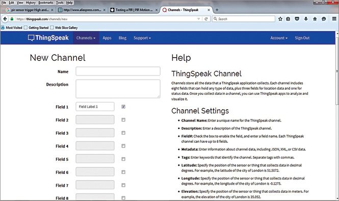
First, sign in to www.thingspeak.com and then create your own channel by creating a field as shown in Fig. 8.
After saving the channel, you will receive channel ID and two API keys—a write API key (it is to be used in our C code) and a read API key (it is used to check the data from website on your smartphone or PC). Make a note of these keys as you will need these later.
Before using the system, ensure that Esp8266 module baud rate is changed to 9600 as most of these have 115200. Also, a Wi-Fi modem with an Internet connection should be kept near your circuit board.
Next, make the following changes in the espIOT.C code:
1. Replace eRocks14 with your own Wi-Fi name
2. Replace erocks2014 with your own Wi-Fi password
3. Replace API key with your own API key received
ESP8266 works on basic AT commands similar to the ones used in any GSM module interfacing project. It can be easily checked and tested from HyperTerminal of Windows. The link to AT commands is www.pridopia.co.uk/pi-doc/ESP8266ATCommandsSet.pdf
In the latest version of ESP8266 firmware, baud rate setting command AT+CIOBAUD is no longer supported. You can replace this command by AT+IPR. The detail of this command can be found on www.esp8266.com/viewtopic.php?f=13&t=718
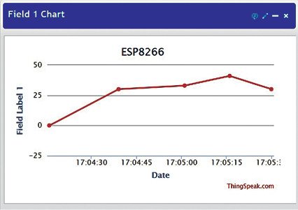
When you open your channel under Data IMPORT/EXPORT section, you will get your API key. Call this link www.api.thingspeak.com/update?key=[THINGSPEAK_KEY]&field1=0 by changing the field value and give any number you want to upload. In Private View section, you will see a graph of the data as shown in Fig. 9.
For checking the results on a smartphone or PC, a link is provided in the respective channel. It would be something like https://api.thingspeak.com/channels/channel_id/feed.json?key=api_key
In this link, API key is replaced by Read API key and channel id is replaced by the user’s channel ID. Copy and paste this link in search bar of the browser in your smartphone or PC. You will get the recorded temperature data information.
If temperature data has been uploaded, you will be able to see the graph here. Temperature data on www.thingspeak.com is shown in Fig. 9. You are now ready to go with your first IoT project.
Applications
This project can be used as a guide for various other related projects for your home systems; not just temperature but also energy consumption and many other interfaces that can be easily checked on your smartphone.
Osho Gera is a second-year B.Tech student, studying at Bharati Vidyapeeth’s College of Engineering, New Delhi


It is very good project. please tell where can i get esp8266 chip. can I use another mcu for this project instead of pic.?
Here’s the reply from the author Osho Gera:
“ESP8266 module is easily available on Internet, and any micro-controller can be used. I have developed the same project on ATmega16.”
hi, by smartphone, do u mean an android apps or just web browser. coz my project require me to make an android apps
can we use regulator ic instead of Logic-level shifter. ??? if yes how ?
No this is the easiest way, of course you can use resistors and transistors for signal level shifting application.
Shall i can get totally assembled project
can I know why you state condition if(x-32<0) at your sending commands part?is there any reason why 32?hope you can explain
Here’s the reply from author Osho to Siti Masliana.
“If you look closely at the ASCII table , you would note that there are 31 characters that include some special characters like \t,\n,the actual characters starts from space i.e ASCII 32 also the output received from the strstr function is in char type pointer. Yes, I could compare with a null object (‘\0’) but I preferred to check with a threshold like space.
I hope this clears the doubt.”
How to insert Wi-Fi module ESP8266 in proteus?
did you manage to insert esp8266 in proteus? i want to do the same.
thanks for you project and am doing this project in lpc2129 Arm 7 please guide me ….
Kindly elaborate your query.
thank for your project here am using the lpc2148 microcontroller please guide me ?
Kindly elaborate your query.
We configure UART for serial communication, we sent “AT” command to wifi ESP01(ESP8266) without logic converter. how to check response command from the wifi module. and logic converter must use or not?? connection for wifi module giving 3.3V from LM1117.
hai sir.shall you give any simple examples
Hi I cannot find appropriate logic level shifter
Kindly tell me about it
For level converter/shifter module you may contact https://www.fabtolab.com/I2C-conveter-module-5v-3v
Hi,
Can you please induce comments for every function what it is doing? Upload it again – it will be a great help.
Thanks
hi Can u pls tell more about changing baud rate of ESP8266
is there any Proteus simulation? Please give some idea to simulate it in Proteus.
Sorry we do not have Proteus simulation right now.
i tried this project using PIC16F877A. while building strcat function is not defined..is it a syntax error i have done the same coding as you did strcat(value,”AT+CWJAP=\”eRocks14\”,\”erocks2014\””); but this is always getting error.
Please see the comments in the code. The ‘ erocks2014’ is the Wifi router name we used during testing. You need to replace it with the name of your Wifi.
can you tell us how to do this project by using ATMEGA16 instead of PIC microcontroller?
You need to do new coding for ATmega16
Can you copy and paste the ‘CODE’ in notepad or MS word and put it in the link? Please…. My MPLAB is not supporting.
Hi, iv put the code in is there a reason u can think of that the ESP8266 only works after flashing the pic ? When i put it off and on again it fails to connect, unless i reflash it.
We are able to burn the program using ardino in pic16f8266A because we do not have pic loader
hello i use pic16f877a is there any problem?
how to change the baud rate of wifi module???
can send the corel draw design
can you upload the code for this project?
what is the output of the this project how to see it ?
The output of the project is temperature value shown in the LCD and also live temperature data graph on the thingspeak.com website.
Why don’t you just use the ESP8266 for this project and drop the PIC proc?. ESP8266 is a complete microprocessor with WiFi which can be easily programmed with the Arduino IDE. Simply use the ESP8266 fitted on one the breakout boards commonly available, this will give you the I/O ports you need for your project.
How can i put program in this circuit?
Hi, I’d like to contact you with academic pouposes.
Where can I e-mail you?
You can email me at [email protected]
Hi, the source code is not getting downloaded. Would you mind sending me that again?
Kindly refresh the page