 Temperature monitoring and control is important in industry environments. Sensors are widely used for measurement of temperature. Usually, a temperature sensor converts the temperature into an equivalent voltage output. IC LM35 is such a sensor. Here we describe a simple temperature measurement and display system based on LM35 sensor and PIC16F877A microcontroller. The temperature in degrees Celsius is displayed on a 16×2 LCD.

Fig.1 shows the functional block diagram of the PIC16F877A-based temperature monitor system. The key features of this system are:
1. Continuous monitoring of temperature with 1-second update interval (which can be varied in the program).
2. Temperature measurement using LM35 precision integrated-circuit sensor.
3. Precise analogue-to-digital conversion using in-built 10-bit analogue- to-digital converter (ADC) of PIC16F877A microcontroller.
Hardware description
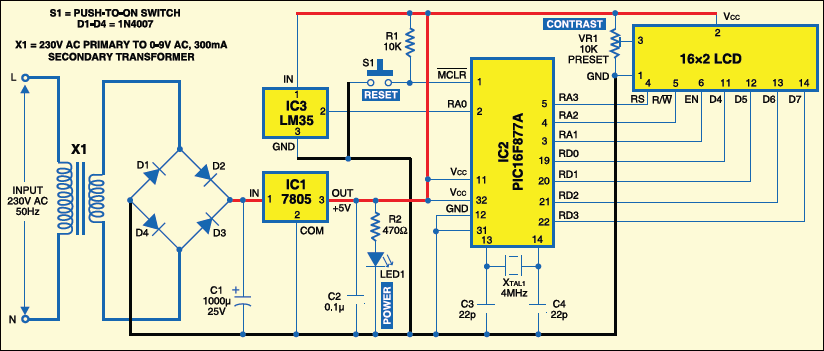
Fig.2. shows the circuit of the temperature monitor system. The circuit mainly consists of the LM35 temperature sensor, PIC16F877A microcontroller and HD44780 controller based 16×2 LCD.

You can also check how to interface LCD with PIC16F877A

The output of the sensor is fed to the internal ADC of the microcontroller. Pin 2 of the microcontroller (RA0/AN0) is channel-1 of the internal ADC. The analogue voltage output of the sensor is converted into its equivalent digital value by the ADC and then its equivalent degree Celsius value is calculated by the software. The calculated temperature value is displayed on the LCD.

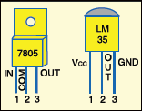
LM35 sensor. Fig.3 shows the pin configuration of LM35. It is a precision integrated-circuit centigrade temperature sensor whose output voltage is linearly proportional to the Celsius (Centigrade) temperature. The LM35 thus has an advantage over linear temperature sensors calibrated in degree Kelvin, as the user is not required to subtract a large constant voltage from its output to obtain convenient Centigrade scaling. For each degree Celsius change in temperature, the sensor output changes by 10 mV.
The sensor can measure temperature in the range of 0 to 100°C, i.e., the output of the sensor varies from 0 to 1000 mV. The LM35 operates over the temperature range of -55° to +150°C, while the LM35C is rated for a -40°C to +110°C range (-10°C with improved accuracy).
Pin layout of the sensor is as follows:
Pin 1-VDD
Pin 2-Output of the sensor
Pin 3-VSS
PIC16F877A microcontroller. IC PIC16F877A is an 8-bit microcontroller with 8k×14-bit flash program memory, 368 bytes of RAM and many other extra peripherals like ADC, universal synchronous asynchronous receiver transmitter, master synchronous serial port, timers, compare capture and pulse-width modulation modules, and analogue comparators. It is based on the reduced instruction set computer (RISC) architecture.
The microcontroller processes the sensor output to compute the temperature in degree Celsius. The internal ADC of the microcontroller is used to convert the analogue output of the sensor into its equivalent digital value.
The internal ADC of the microcontroller has eight channels of analogue input and gives 10-bit digital output. In this project, the reference voltage to the ADC is the same as the supply voltage to the microcontroller, i.e., 5V. The resolution of the ADC can be calculated as follows:
Resolution = Vref / (1024-1) …(as it is a 10-bit ADC)
= 5/1023
= 4.887 mV
It means that for 4.887mV change in the analogue input, the ADC output changes by binary ‘1’ with a reference voltage of 5V.
Analogue output of the sensor at its pin 2 is connected to Port A at RA0 for conversion into digital equivalent.
The LCD. A 16×2 LCD based on HD44780 controller is used for displaying the temperature. The control lines EN, R/W and RS of the LCD module are connected to pins RA1, RA2 and RA3 of Port A of the microcontroller, respectively. The commands and the data to be displayed are sent to the LCD module in the nibble mode from Port D of the microcontroller. The higher four bits of the LCD (D4 through D7) are connected to the lower nibble of Port D (RD0 through RD3).
Software description
The software code is written in ‘C’ language and compiled using Hitech C cross compiler in MPLAB IDE. The software performs the following operations in an infinite loop:
- Initiate analogue-to-digital conversion and obtain the result
- Calculate the equivalent voltage value from the ADC result
- Calculate the temperature in degree Celsius from the voltage value
- Displaying the temperature monitor value on the LCD
The voltage output (in volts) of the sensor is:
(ADC result × 5) / 1023
The temperature in degree Celsius is:
Sensor output × 1000 / 10 = Sensor output × 100
The Hitech C cross-compiler provides floating-point library support that is required for doing the above calculations.
MPLAB IDE and Hitech C compiler. MPLAB IDE is a very powerful software development tool for Microchip products (microcontrollers). It is available for download at www.microchip.com free of cost. It consists of tools like text editor, cross-assembler, cross-compiler and simulator.
Hitech C cross compiler is meant for Microchip PIC10/12/16 series of microcontrollers. Its Lite edition comes free with newer versions of MPLAB IDE like MPLAB v8.2 and v8.3. It can also be downloaded for free from www.htsoft.com.
Compiling the program using MPLAB IDE. The steps follow:
1. Create project file and add source files. In the menu bar, click Project→ Project Wizard. The project wizard dialogue box appears. Click ‘Next.’ In ‘Next’ window, select the device as PIC16F877A from the drop-down menu. Click ‘Next’ and select ‘Hitech Universal Tool’ suite from the drop down menu. Click ‘Next,’ name your project file as ‘tempr’ and specify its location. The file is automatically saved with ‘.mcp’ extension. Click ‘Next’ and add source files tempr.c, lcd.c and delay. c to your project. If you want to create the source files on your own, you can skip the above step. Click Next→ Finish button. Now your project is created and the source files are added to your project.
2. Create and add source files of your own. After creating the project, proceed with typing the code. Open a new text file by clicking ‘New’ in ‘File’ menu. Type the code in the text editor and save it with ‘.c’ extension. You can create source files tempr.c, delay.c and lcd.c in this manner. After typing and saving the code, you have to add the source files to your project. In ‘Project’ menu, click ‘Add Files to Project’ and then add the files by browsing them from the location they are saved in.
3. Configure the system. To configure features like type of oscillator and WDT, click ‘Configure’ menu and then click ‘Configuration Bits.’ In the configuration bits window, select the type of oscillator as XT, and disable all other features like watchdog timer, power-up timer and brownout detect.
4. Compile the project. To compile the software, click ‘Build’ option in ‘Project’ menu. The software is compiled and ‘Build Successful’ message appears in the output window. After successful compilation of the program, the file tempr.hex is generated.
Downloading the software into the chip. After compiling the software, the hex file generated can be downloaded into the chip either using a locally made programmer (like JMD programmer) or Microchip’s programming kit (PICKit2, PICKit3, ICD2, ICD3, etc).
We have used Microchip MPLAB ICD2 (in-circuit debugger) to burn the program into PIC16F877A microcontroller.
The programming can be done from MPLAB IDE itself by selecting the kit (MPLAB ICD2) from ‘Programmer’ menu in the menu bar. If you use a JMD programmer, the hex file can be downloaded into the chip using WinPic800 software. The configuration bits have to be separately configured in WinPic800.
Construction
A single-side, solder-side PCB layout of the temperature monitoring system is shown in Fig.4(View as PDF) and its component layout in Fig.5(View as PDF).
Download PCB and component layout PDFs: click here
A 230V AC primary to 0-9V AC secondary step-down transformer is used to step down the 230V mains supply. The output of the transformer is rectified using a bridge rectifier consisting of diodes D1 through D4 and regulated to 5V using 7805 voltage regulator. The glowing of the LED (LED1) indicates the presence of 5V supply in the circuit.
The analogue output of the temperature sensor LM35 (IC3) from its pin 2 is connected to RA0/AN0 pin of PIC16F877A microcontroller (IC2). A 4MHz crystal (XTAL1) is connected to pins 13 and 14 of the microcontroller. The 16×2 LCD is interfaced with the microcontroller using Port A and Port D. The control signals for the LCD are provided using Port-A pins RA1, RA2and RA3. The command and data for the LCD are provided using Port-D pins RD0 through RD3. The remaining power supply connections are as shown in Fig.2.
EFY note. The source code and other relevant files of this article are included in the link below.
Download Source code: click here


Please fix source code link
We have updated the source code. Please check.
do u implement it physically?
Yes, the code was tested on hardware
I still can’t download the source code!
super done job good job…but i have small doubt of that code ..what is the need of ch4 and f1=num-temp.everytime f1 will be zero.
where do i find the code?
The source code is present on the last page of the article.
Where did I get protecus modle of this sensor