


Precise determination of null point in AC/DC bridges helps us to evaluate accurate values of circuit components like L and C. Here’s a null detector that has the following merits:
• Same two input terminals of the detector can be employed for both DC and AC signals.
• There is no moving part like galvanometer. An array of ten LEDs operating in bar mode serves as visual means for detection of balance condition.
• The sensitivity of the instrument is quite high. Even when the out of balance is as low as 25 µV, detection is possible. This serves the purpose well for most measurements.
As is known, a sensor can be employed as detector for DC signal. It seems interesting at first sight that we can employ the same DC instrument in an AC circuit if we rectify the signal prior to applying it to the galvanometer. But here comes the problem. A silicon diode gets cut-off when the applied voltage falls below 0.7 volt and the galvanometer would read zero, although you are then far from the true balance point. The solution is to develop a precision rectifier using operational amplifier. This is the central theme of the null detector circuit presented here.
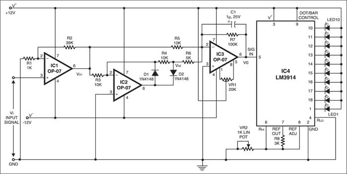
FET input operational amplifier IC1(Op07), with very small offset voltage and extremely low bias current, serves as a non-inverting amplifier to increase the input signal level as shown in the figure. The gain of the amplifier is:

A=(1+R2/R1)=(1+39k/1k)=40...(1)
If Vi represents the input voltage and Vo1 the output voltage of amplifier IC1, we have
Vo1=AVi …(2)
IC2 is used as a precision half-wave rectifier and the output of the rectifier is

Vo2 = –AVi, if Vi is positive
 = 0, if Vi is negative ...(3)
IC3 plays a dual role. It acts as an inverting type adder and also as a low-pass filter. Low-pass filtering action is due to capacitor C1 in parallel to R7. For DC and low-frequency signals, the reactance of the capacitor is extremely high and the effective impedance in the feedback path is close to R7. For high frequencies, the capacitor looks short and the output is close to 0V. This is the low-pass filter action. The cut-off frequency of the low-pass filter is:
![]()
 Hence the operating frequency of the detector for AC signals must be kept above cut-off frequency fc. As far as only the adder action is concerned, output Vo is given by:
Vo = (R7/R5 . Vo1)+(R7/R6 . Vo2) ...(5)
 Or,
 Vo = –(10Vo1 +20Vo2) ...(6)
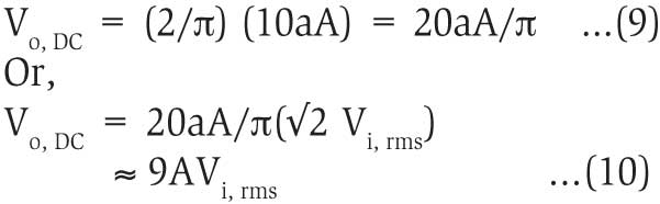
For DC voltage, Vi =±V volt. Therefore, it follows:
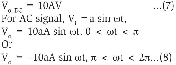
Because of low-pass filtering action, the actual output is a positive DC voltage with very little ripple:
IC LM3914 (IC4), commonly known as dot/bar display driver, has a set of ten comparators that detect ten voltage levels and drive ten LEDs accordingly. Here, IC4 is used in bar mode.
The internal circuitry of IC4 develops reference voltage VREF of 1.25V between its pin 7 (REF OUT) and pin 8 (REF ADJ). A nominal current (IADJ) of typically 0.075 mA (maximum 0.120 mA) flows out of pin 8. The voltage difference between pin 6 (RHI) and pin 4 (RLO), here grounded, is applied to an internal string of ten 1k resistors and sets up ten evenly spaced comparator levels. With reference to the figure, the voltage at pin 6 is given by:
VRHI = (VREF/R8 + IADJ)VR2/(1+VR2/10) volt ...(11)
where all resistor values are in kilo-ohm and current in mA.
In the present case, the value of R8 is 3 kilo-ohms and VR2 is adjusted such that VRHI becomes exactly 100 mV. (The approximate value of VR2 is 0.2 kilo-ohm.) The output DC voltage of IC3 is routed to pin 5 (SIGNAL IN) of IC4. As a consequence, the first LED will turn on if the voltage at pin 5 just exceeds 10 mV, followed by glowing of all the succeeding LEDs, one by one, for every 10mV rise in this voltage level. This provides visual means for precise determination of balance point.
Current I1, drawn out of pin 7, determines the brightness of the LEDs. Each glowing LED draws a current approximately ten times of I1, viz,
10 VREF /R8 ≈ 4 mA.
For adjustment, make input voltage Vi=0. Connect a digital voltmeter in 200mV DC range between pin 5 of IC4 and ground (GND). Adjust the offset null by varying VR1 until the voltmeter reads zero.
Now connect a DC or AC signal source between the input pin 3 of IC1 and ground. Adjust the input voltage such that the voltmeter reads exactly 100 mV at pin 5 of IC4.

Sir
If any tools, dedector or equipment available to find out null point in 320 kV pot line. Please reply.
Hi
Is there any circuit that can work as Null Detector for Wheatstone DC Bridge with Precision step in Microampere. Very nice topic, thank you for sharing best regards Nikos