


The MAX232 has two internal charge pumps that convert +5V into ±10V (unloaded) for RS-232 driver operation. The first converter uses capacitor C8 to double the +5V input to +10V on capacitor C10 at pin 2. The second converter uses capacitor C7 to invert +10V to -10V on capacitor C6 at pin 6.
All the serial communication is controlled through special-function register SCON. This register contains mode-selection bits, ninth data bit for transmit and receive (TB8 and RB8), and serial-port interrupt bits (TI and RI). Serial communication requires standard baud rate. Timer-1 is configured in auto-reload mode to generate baud rate. The baud rate is determined as:
Baud rate = (2SMOD × Oscillator frequency) / (32×12×(256 – TH1))

The 230V, 50Hz AC mains is stepped down by transformer X1 to deliver a secondary output of 9V, 500 mA. The transformer output is rectified by a full-wave rectifier comprising diodes D1 through D4, filtered by capacitor C1 and regulated by IC 7805 (IC3). Capacitor C2 bypasses the ripples present in the regulated supply. LED1 acts as the power indicator and R2 limits the current through LED1.
Construction and testing

An actual-size, single-side PCB for the microcontroller-based pulse counter is shown in Fig. 2(View as PDF) and its component layout in Fig.3(View as PDF). Assemble the circuit on a PCB as it minimises time and assembly errors. Carefully assemble the components and double-check for any overlooked error. Connect the assembled circuit to the COM port of the computer.
Download PCB and component layout PDFs (Fig. 2, 3): click here
The accumulated pulse count transferred is sent to the PC through the COM port using the HyperTerminal program. To open the HyperTerminal program, go to Start → Programs → Accessories → Communications → Hyper Terminal. You will see a window as shown in Fig. 4.
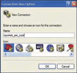
Type the desired name and click ‘ok.’ Select a COM port (refer Fig. 5) while ignoring the other options and click ‘ok.’

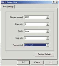
Now select the baud rate as ‘9600,’ data bits as ‘8,’ parity as ‘none,’ stop bits as ‘1,’ flow control as ‘Xon/Xoff’ and click ‘ok’ (refer Fig. 6).
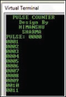
The microcontroller counts the received pulses and sends the pulse count to the hyper terminal and LCD. You will see a message on the screen as shown in Fig. 8. Simultaneously, the pulse count appears on the LCD.
Software
The software for this project is given at the end of this article. It is written in ‘C’ language and compiled using Keil μVision4 compiler. Burn the generated hex code into the microcontroller using a suitable programmer.
In the software, first enable timer and serial interrupts. Then configure the timer by mode and reload value to give the correct speed (9600 bits per second). SCON gives the necessary UART signal and your data is sent serially. When port pin P3.5 (T1)goes low, the internal counter increases by one. This count is displayed on the LCD as well as hyper terminal of the PC.
Download source code: click here

Hey himanshu how can I contact you
The source code link is broken kindly fix it.
Source code link is not working.
Thank You for your comment. The source folder has been updated. You can download now.