The regular 16×2 LCD can display characters of only certain dimensions. A graphical LCD (GLCD), on the other hand, can display custom graphics. GLCDs are therefore highly suitable for mobile and industrial applications.
Here we present a simple graphical LCD interface circuit along with a set of software tools using which you can display any graphics of your choice on the GLCD. Using the software tool chain, any graphics, text or picture can be designed on the computer and then transferred to the GLCD.
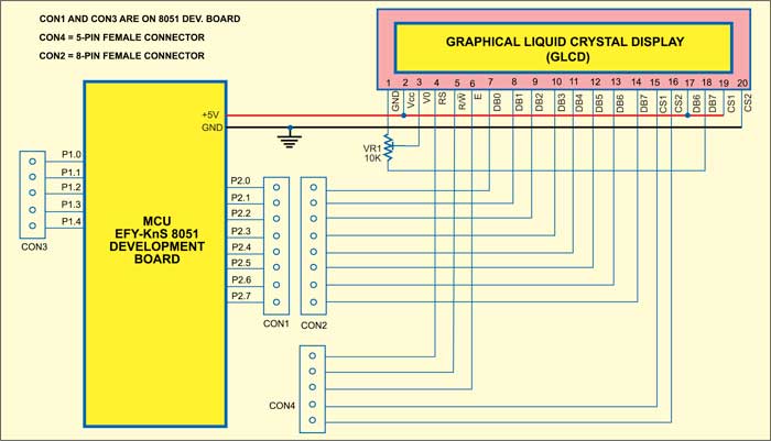
As shown in figure, the circuit is built around EFY-KnS 8051 development board and a GLCD (JHD12864E).
All the microcontroller ports are open and available for interfacing on the KnS board itself. The GLCD is connected to the board using an 8-pin female connector (CON2) and a 5-pin female connector (CON4) that are soldered to the LCD through wires as shown in figure. The circuit works off 5V regulated power supply, which can be taken from the development board through an external connector.
Port 2 on the development board is used for data inputs (DB0 through DB7). Three pins of Port 1 are used for register select (RS), read/write (R/W) and enable (E), while two pins of port 1 are used for CS1 and CS2 of the GLCD.
Here we have used a 128×64 GLCD, which is divided into two equal halves. Each half is controlled by a separate controller and consists of eight pages. CS1 and CS2 are controller-select pins. Each page consists of 8 rows and 64 columns. So two horizontal pages make 128 (64×2) columns and eight vertical pages make 64 rows (8×8).
The software is written in ‘C’ language and compiled using Keil version 4.0 demo platform. Steps to burn the program in the chip are very simple and mentioned in the manual provided with EFY-KnS 8051 development board.

The working of the circuit is simple. Simply use below-mentioned steps to design a picture, say, smiley, and convert it into hex code:


