


 This PIC16F877A microcontroller-based quiz controller, designed for up to six players or teams, is suitable for school and college quiz competitions. It is similar to a fastest-finger-first system in which the player who presses the button first gets the first chance to answer the quiz.
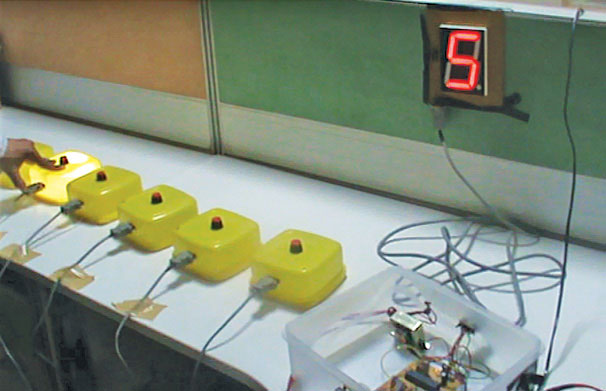
Here, each team is assigned a unique number and provided with a pushbutton switch. As soon as a question is asked by the quiz master, any of the participating teams can press the button and give the answer within the allotted time. A buzzer sounds and a big 12.7cm (5-inch) 7-segment display shows the number of the team that presses their pushbutton switch first. Author’s prototype is shown in Fig. 1.
Circuit and working
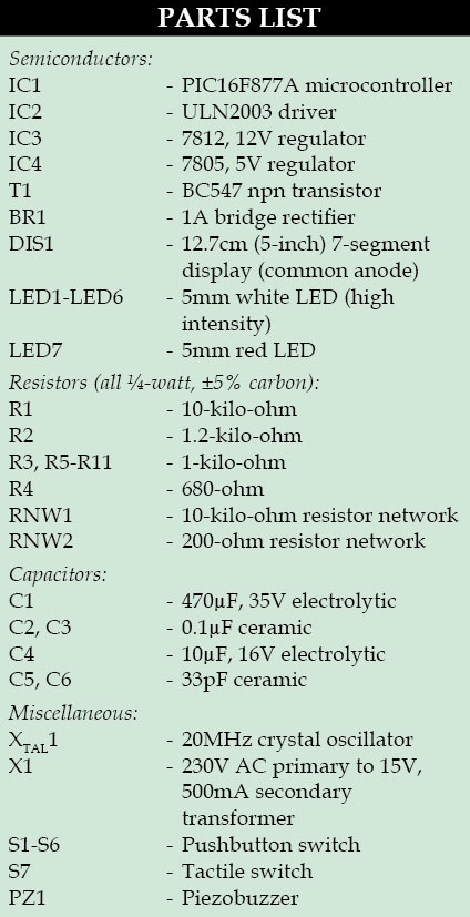
As shown in Fig. 2, the quiz game controller circuit is built around the popular PIC16F877A microcontroller (IC1), driver ULN2003 (IC2), transistor BC547 (T1), 7-segment display (DIS1), some LEDs and switches.

PIC16F877A
This microcontroller, which forms the heart of the circuit, has 8-bit processor with 8kB Flash memory, 368-byte data memory and 256-byte EEPROM. In addition, it has three timers. A 7-segment (common-anode) display is connected to the PIC controller through buffer ULN2003 on port C (RC0-RC6).
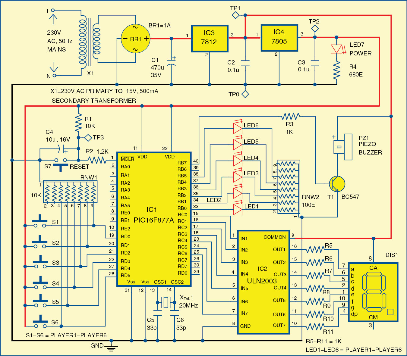
 Six pushbutton switches are connected to port D (RD0-RD5) of the microcontroller. This port is used as the input port. The logic values of these switches are scanned by the program through this port at a very fast rate of about 6 microseconds. The microcontroller keeps scanning the positions of the switches and, when a switch shows logic 1, it sends a signal to port B (RB7) and the buzzer sounds.
Port B of the microcontroller acts as output port for the LEDs also. Six LEDs (LED1 through LED6) connected to port pins RB0 through RB5 of IC1 are used as visual indications. For example, if the third team presses the switch first, LED3 will glow along with sounding of the buzzer, and at the same time digit ‘3’ will be displayed on DIS1.
Switch S7 is connected to pin 1 of microcontroller for manual reset. Resistors R1 and R2 and capacitor C4 form the power-on reset circuitry.
ULN2003
The 7-segment display DIS1 (SUNR400CA or its equivalent) is driven by ULN2003 driver IC2. Pins RC0 through RC6 of microcontroller are connected to input pins IN1 through IN7 of IC2. Its output pins OUT1 through OUT7 are connected to the segments ‘a’ through ‘g’ of DIS1.
Power supply
The power supply is derived from 230V AC mains primary to 15V, 500mA secondary transformer X1. Bridge rectifier module BR1 rectifies secondary output of the transformer, capacitor C1 filters it and sends to input of 7812 regulator IC3. The 12V regulated DC output from IC3 is sent to input of 7805 regulator IC4 to power buzzer and DIS1. The 5V DC from 7805 powers the microcontroller.
Software
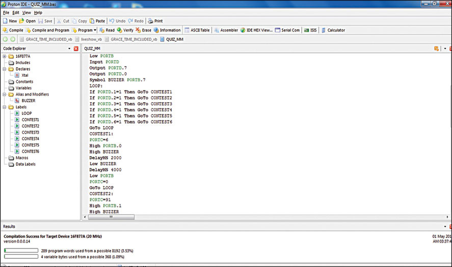
The program for microcontroller is written in Basic and compiled using Proton IDE v2.0. After compilation of the code (quiz_mm.bas), if everything’s fine, you will see ‘Compilation Success for Target Device 16F877A (20MHz)’ message at the bottom of the screen, as shown in Fig. 3. The hex code generated by Proton IDE is used to burn into the PIC16F877A using PICSTART Plus programmer.
Construction and testing
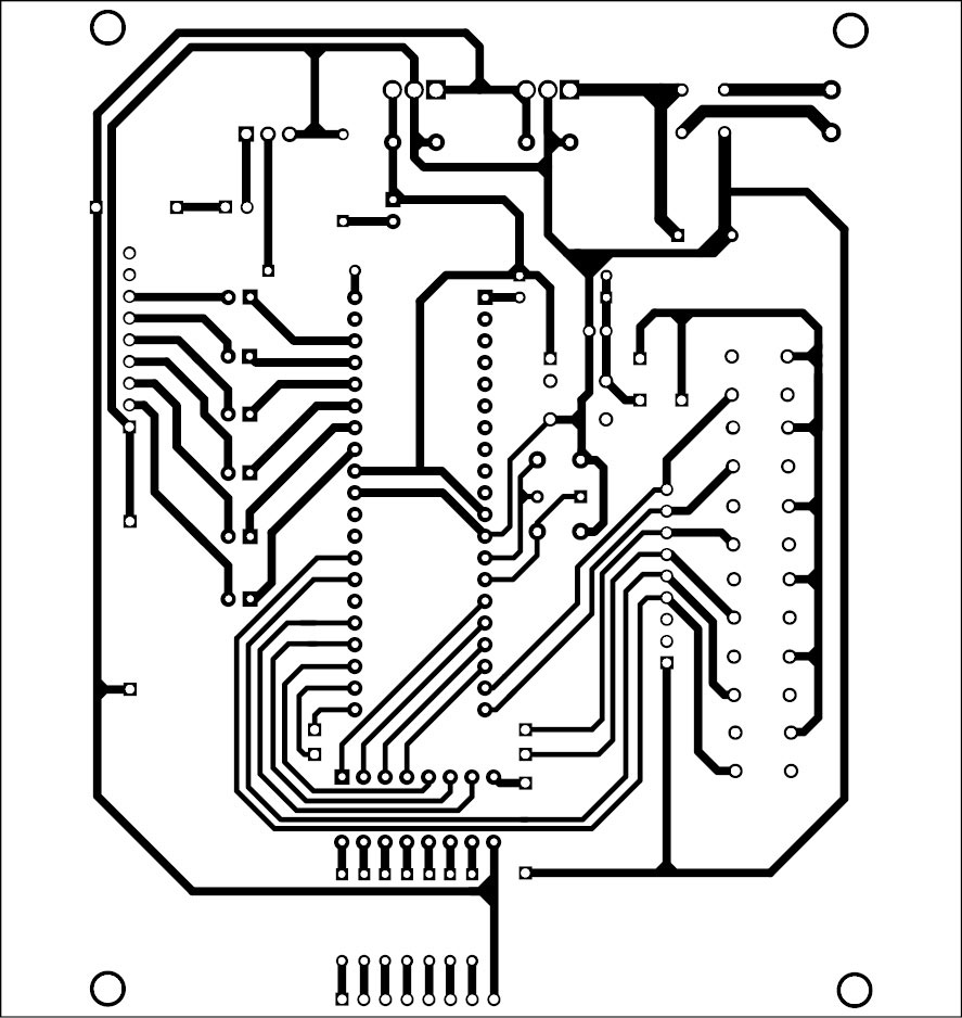
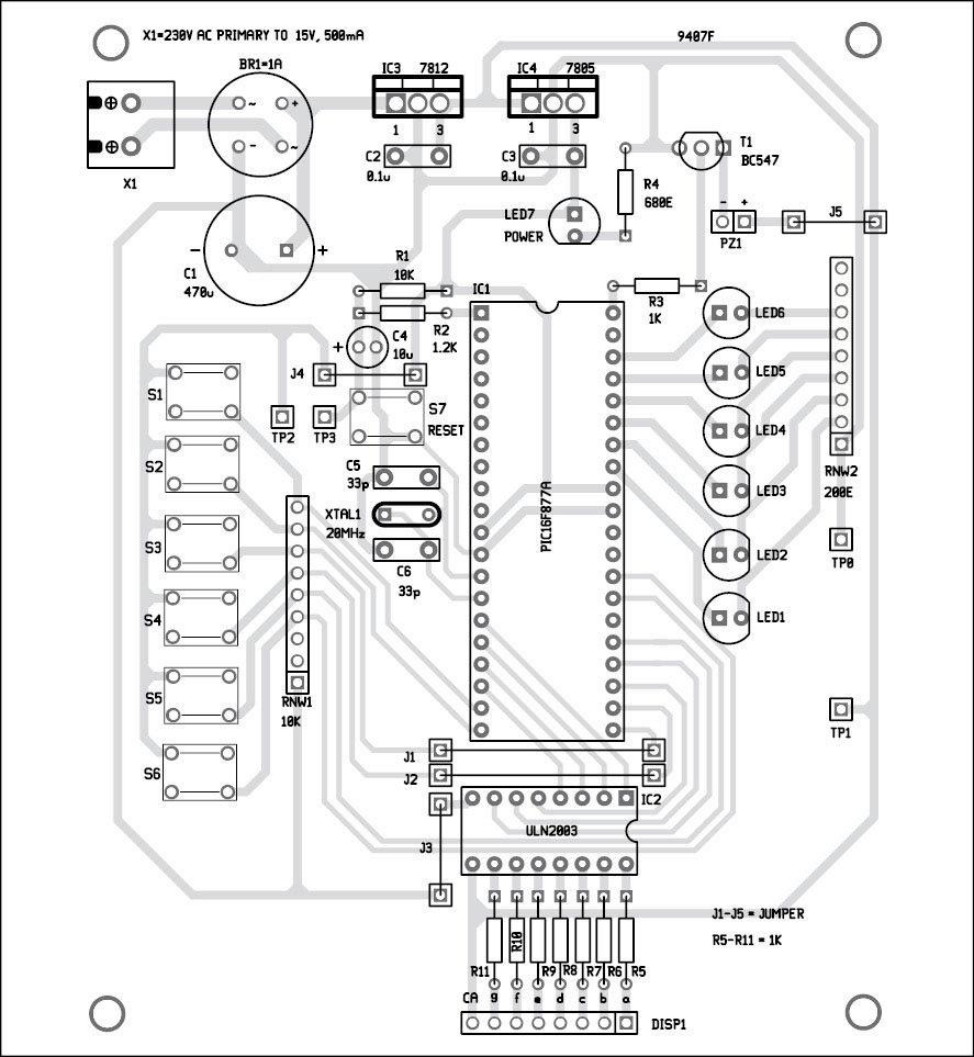
An actual-size, single-side PCB layout for the circuit is shown in Fig. 4 and its component layout in Fig. 5. All the components are easily available in electronics components shops. After assembling of the components properly on the PCB, power supply connections should be checked.
Install the 7-segment display DIS1 suitably so that it is visible to the quiz master and the audience. It requires at least eight wires to connect to the PCB. Connection detail for each segment (‘a’ through ‘g’) is provided in Fig. 5 at DISP1. Next, install all six switches (S1 through S6) at different locations where the six contesting teams can reach them. House each switch and its corresponding LED in a transparent enclosure, so that when you press the switch and LED glows, it is visible to the quiz master.
Switch on the power supply to start the quiz. On pressing any switch (S1 through S6), the corresponding number (1 through 6) should appear on DIS1 and the buzzer should ring. Simultaneously, the corresponding LED near the switch should glow. The LED and display switch off after six seconds while the buzzer stops ringing after two seconds.
When a question is asked by the quiz master, any team can respond by pressing their switch. The switch first pressed is recognised by the microcontroller. Any other switches pressed thereafter do not get registered. So the team who pressed the button first can be allowed to give the answer.
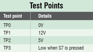
For any problem in the display you can press reset switch S7 momentarily and check again. For further troubleshooting, you can also verify the voltages at various points given in the test points table.
Download PCB and Component Layout PDFs:click here
Download Source Code: click here
Dr D.K. Kaushik is principal and Ashok Sharma is technical assistant at Manohar Memorial (P.G.) College, Fatehabad (Haryana)

Respected sir I want computer quiz software with buzzer buttons where can i get plz inform us at [email protected]
Hello sir
May I know ready PCB available for this project. If available I can buy components and do assembly myself.
Thanks
Guru
Gentelmen
Could I ask please is it possible to add two more switches and if so which pins would I use.?
Best regards
Chris DeBanks