 The World Health Organization (WHO) recommends that everyone should rub their hands with soap for at least 20 seconds before washing with water to prevent transmission of the novel Corona virus, which is again on rise, in addition to social distancing. The 20-second period can be checked with wristwatches and the stopwatches on mobile phones, but these are not convenient to use while washing hands. This proposed circuit rings a buzzer for 20 seconds and switches on an LED for audio as well as visual indication (for those with hearing issues).
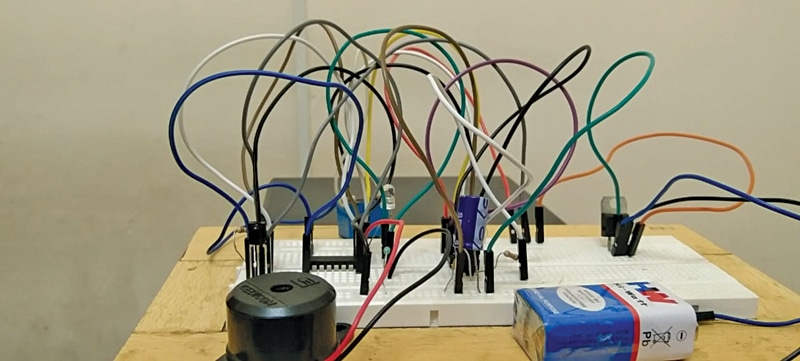
The author’s prototype is shown in Fig. 1.

T=1.1RC
where R=R2=18k and C=C2= 1000µF.
So, time (T) is equal (=1.1×18k ×1000µF) to around 20 seconds.
The infrared receiver TSOP1738 generates an active-low output. When the remote is targeted at TSOP1738 and any key is pressed, input pin 1 of ULN2003 relay driver gets activated and drives the relay. As a result, IC2 produces 20-second output for switching on LED1 as well as the buzzer.
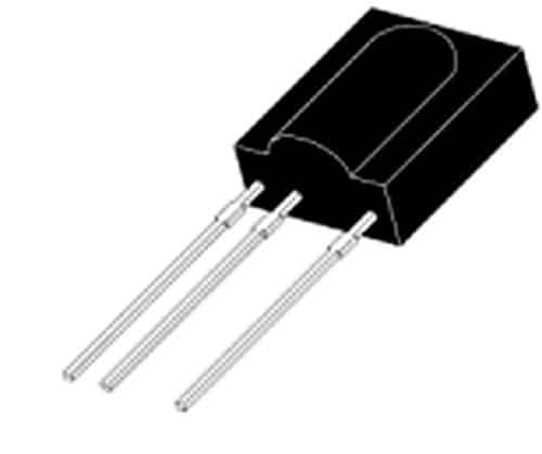
A series of TSOP17XX receivers is available with divergent carrier frequencies for use in television sets, DVD players, etc, to receive the signals from their remote controls. TSOP1738 is a commonly used infrared receiver; it has a PIN diode, preamplifier, and internal filter for the PCM frequency. The carrier frequency of TSOP1738 is 38kHz. An image of TSOP1738 is shown in Fig. 3.
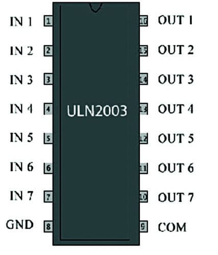
Relay driver ULN2003 (IC3) is used here to drive 5V relay RL1. Pin diagram of ULN2003 is shown in Fig. 4.
Working of the circuit is simple. The remote may be fixed or kept near the wash basin. Whenever anyone goes to wash hands, the remote may be used to switch on the LED and the buzzer for 20 seconds, so the person can rub hands with soap till the LED glows and the buzzer sounds. After that the person may wash the hands with water.
| Parts List | |
| Semiconductors: | |
| IC1 | – LM7805, 5V voltage regulator |
| IC2 | – NE555 timer |
| IC3 | – ULN2003 relay driver |
| LED1 | – 5mm LED |
| Resistors (all 1/4-watt, ±5% carbon): | |
| R1 | – 1-kilo-ohm |
| R2 | – 18-kilo-ohm |
| R3 | – 330-ohm |
| R4 | – 15-kilo-ohm |
| Capacitors: | |
| C1 | – 0.01μF ceramic disk |
| C2 | – 1000μF, 25V electrolytic |
| C3 | – 10µF, 25V electrolytic |
| Miscellaneous: | |
| CON1 | – 2-pin connector |
| BZ1 | – Buzzer |
| RL1 | – 5V SPDT relay |
| – TSOP1738 sensor | |
| – 9V battery/9V DC | |
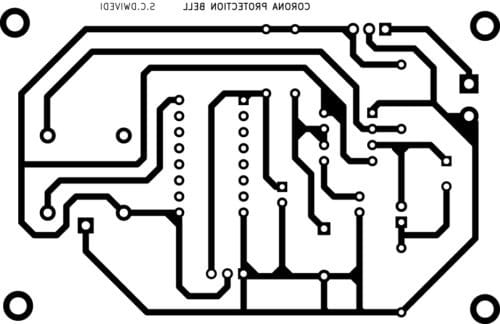
An actual-size, single-side PCB layout for the circuit is shown in Fig. 5 and its component layout in Fig. 6. After assembling the circuit on PCB, enclose it in a suitable box.
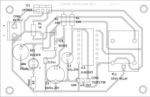
Fix TSOP1738, LED1, and CON1 in front of box. Fit the 9V battery inside the box and the buzzer either inside or on back side of the box. Make a hole in front of TSOP178 in such a way that when you press remote its signal should fall on it.
Download PCB and Component Layout PDFs: click here
Rakesh Jain has master’s degree in VLSI and B.E. degree in Electronics and Communication. He currently works as Assistant professor in ECE Department in Geetanjali Institute of Technical Studies, Udaipur. His research areas are sensors and microcontrollers, and he has 23 copyrights and 3 Indian patents to his credit.


