


 Remote controllers for various audio/video systems are usually provided with a power ‘on’/‘off’ or standby-mode selector button. But turning the system off from the remote handset actually does not cut off the whole system from mains. Some circuitry inside the system continues to get power from mains even when the power is turned off using the remote handset. One needs to turn off the mechanical switch provided on the system’s front panel or wall outlet in order to turn off the entire system.
Also, accessories like TV boosters, stabilisers and additional ampli-speaker systems cannot be turned off from the remote handset. And it is very annoying to get out of bed to switch off mains after watching some programme on TV or listening to music.
The remote controlled power-off switch circuit given here can disconnect the entire system along with the accessories, including the circuit itself, from mains using the remote for the audio or video systems.

Remote Controlled Power-Off Switch Circuit
The circuit consists of a timer IC NE555, a decade counter IC HCF4017, three BC548 transistors, an infrared (IR) sensor IC TSOP1738 and a few discrete components. Transformer X1, diodes D1 and D2, and capacitor C1 form power supply for the circuit. Zener diode ZD1 provides regulated voltage to IR sensor TSOP1738 (IC3).
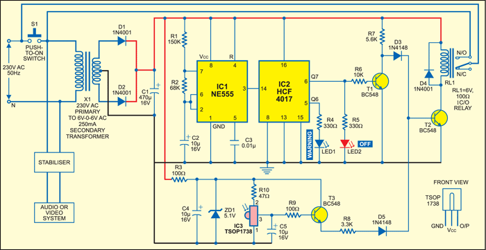
Timer IC NE555 (IC1) is configured as an astable multivibrator that produces a clock pulse every two seconds. The clock pulse is fed to decade counter IC HCF4017 (IC2), whose Q7 output is inverted by transistor T1 and applied to the base of transistor T2 to drive the relay.

The output of sensor IC3 is used to drive transistor T3 and activate the relay via transistor T2.
The outputs of transistors T1 and T3 are O Red and the resultant is applied to transistor T2. Thus if any one or both the inputs connected to the base of transistor T2 are high, relay RL1 energises. The relay de-energises if both the inputs to transistor T2 go low.
Circuit operation
Initially, to switch on mains supply for the audio/video system and the circuit itself, push – button switch S1 is pressed momentarily.
Normally, the output of IR receiver module IC3 is high when it is not being activated by a remote, and the relay energises to close the N/O contact and place a short across switch S1. This circuit and the load continue to get power through the N/O contact of relay RL1 even when push button S1 is released.
At the same time, the output of IC2 starts scrolling around its output pins, i.e., pins 5 and 6 go high and low alternately for the clock pulses received. When Q6 output goes high the ‘warning’ LED (yellow) glows, and when Q7 output goes high the ‘off’ LED (red) glows.
Yellow LED (LED1) indicates that it’s time to switch off the audio or video system.
The entire system can be turned off by pressing any key on the handset once when the red LED (LED2) is glowing. The reason is that red LED2 glows when the Q7 output of IC2 is high. Due to this, the output of transistor T1 is low. Now if any key on the remote handset is pressed, the sensor output goes low for a while. Since both the inputs connected to the base of transistor T2 become low at this time, the transistor stops conducting and the relay de-energises. As a result, the N/O contact of the relay opens to switch off the circuit and the load connected across the transformer’s primary winding.
Any normal operation (increasing/ decreasing volume, changing channels, etc) can be performed when either both the LEDs are ‘off’ or the remote is not oriented towards IR receiver module IC3.
The article was first published in January 1997 and has recently been updated.
