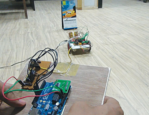
 We have seen many projects where a robot is controlled by a remote controller. Here we describe a robot (robocar) that can be steered in any direction just like you drive your car. Wireless steering senses the motion and transmits corresponding instruction to control the robot through RF communication. The robot also has an obstacle detection and avoidance system implemented. Fig. 1 shows prototypes of the wireless steering and the controlled robot.
Circuit and working
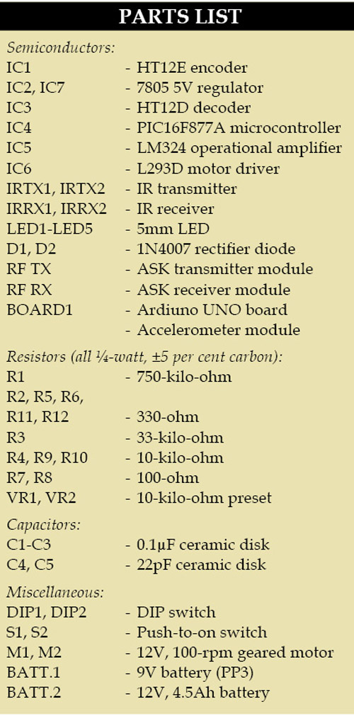 Fig. 2 shows the block diagram of the complete project. The movement of the steering is sensed by the accelerometer. The data from the accelerometer is processed by Arduino Uno board and corresponding instructions transmitted through the RF transmitter to control the robot. The robot receives the instructions and the MCU section drives motors corresponding to instructions received. Obstacle detectors sense any object in the way and intimate the microcontroller to stop forward motion.
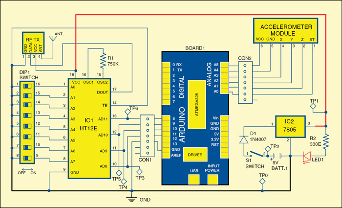
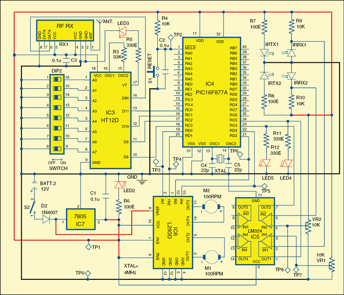
Figs 3 and 4 show circuits of the wireless steering and the robot, respectively.
Wireless steering
It is built around Arduino Uno board (Board1), encoder HT12E (IC1), regulator 7805 (IC2), 433MHz RF transmitter module, accelerometer module and a few discrete components. Pins A0, A1, A2, A3, A4 and A5 of Board1 are connected to pins ST, Z-axis, Y-axis, X-axis, GND and VCC of the accelerometer module, respectively.
The microcontroller of Board1 receives data for x, y and z axes from the accelerometer. This data is continuously compared with predefined values for each axis. If the received value for any axis crosses the predefined value, a corresponding 4-bit code is generated at pins 8 through 11. This code is encoded through IC1 and transmitted using RF transmitter module.
Accelerometer module
An accelerometer is an electromechanical device that measures acceleration of anything that it is mounted on. The accelerometer module used here is based on ADXL335 triple-axis accelerometer from Analog Devices. The sensor has a full sensing range of ±3g.

Arduino Uno board
Arduino is an Open Source electronics prototyping platform based on flexible, easy-to-use hardware and software. It is intended for artists, designers, hobbyists and anyone interested in creating interactive objects or environments.
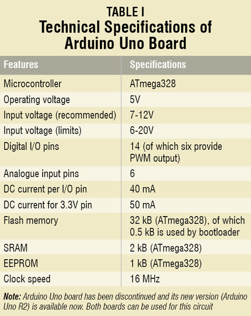
Arduino Uno is a board based on ATmega328 microcontroller. It consists of 14 digital input/output pins, six analogue inputs, a USB connection for programming the on-board microcontroller, a power jack, an ICSP header and a reset button. It is operated with a 16MHz crystal oscillator and contains everything needed to support the microcontroller. It is very easy to use as the user simply needs to connect it to a computer with a USB cable or power it with an AC-to-DC adaptor or battery to get started. The microcontroller on the board is programmed using Arduino programming language and Arduino development environment.
Robot
It comprises an RF receiver module, decoder HT12D (IC3), microcontroller PIC16F877A (IC4), operational amplifier LM324 (IC5), motor driver L293D (IC6), regulator 7805 (IC7) and a few discrete components.
Data transmitted from the wireless steering is received by the RF receiver module and further decoded by IC3. Decoded data is fed to pins RC0 through RC3 of microcontroller IC4. Identical addresses can be selected for the encoder and the decoder through switches DIP1 and DIP2. The outputs from pins RD0 through RD3 of the microcontroller are fed to IN1 through IN4 of driver IC6 to drive motors M1 and M2, respectively. Enable pins EN1 (pin 1) and EN2 (pin 9) are kept high for always-enabled output.
Regulator IC7 is used for 5V regulated supply. 12V battery supply is directly connected to pin 8 of motor driver IC6. Two IR transmitter-receiver pairs are used for obstacle detection. Presets VR1 and VR2 are used to set the reference voltage for the two operational amplifiers in IC5, respectively.
When the robot reaches close to an obstacle, IR beam reflected off the obstacle is detected. Voltage at the inverting pins 2 and 6 of IC5 goes lower than the reference voltage and the output of both the operational amplifiers becomes high. The same is indicated by LED4 and LED5.
Output from pins 1 and 7 of IC5 is fed to pins RC5 and RC4 of microcontroller IC4, respectively. Microcontroller controls the motor corresponding to the data received from the transmitter and obstacle-detection system. Any obstacle will block forward movement but motion in the other directions is still allowed.
Working of the circuit is straightforward. Hold the wireless steering in your hands as shown in Fig. 1 and adjust the tilt to obtain no-movement position. Now if you move the steering to the left and values from the accelerometer corresponding to that axis increase above the predefined value, the transmitter transmits the code for left movement to the robot. This code is received by the receiver of the robot and the microcontroller drives the motors to turn the robot to the left. Similarly, to move the robot in another direction, tilt the steering in that direction.
Software
The wireless steering is built around Arduino Uno board. Arduino Uno is programmed using Arduino IDE software. ATmega328 on Arduino Uno comes pre-burnt with a boot loader that allows you to upload new code to it without the use of an external hardware programmer. It communicates using the original STK500 protocol. You can also bypass the boot loader and program the microcontroller through ICSP (in-circuit serial programming) header, but using boot loader programming is quick and easy. Select Arduino Uno from ‘Tools→Board’ menu (according to the microcontroller on your board) in Arduino IDE and burn the program through standard USB port in the computer.
The source program for the robot is written in ‘C’ language and compiled using MPLAB IDE for the robot. Burn the hex code into the microcontroller using a suitable programmer. Program execution starts by initialising the input and output ports. The program checks the received data for forward, backward, left and right movements and gives corresponding control signals to the motor driver.
Download source code: click here
Construction and testing
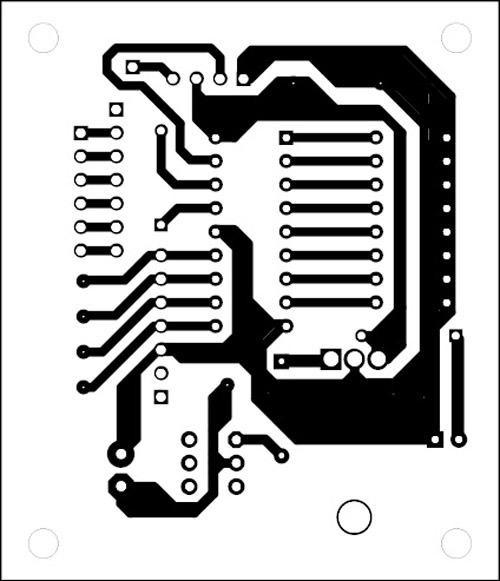
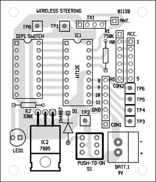
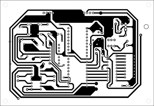
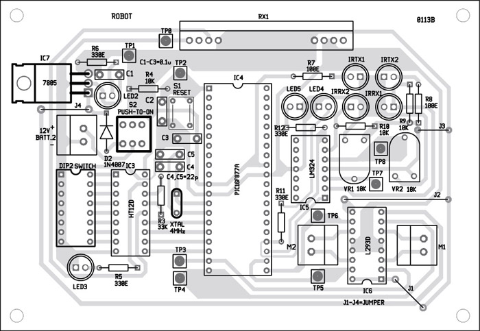
A single-side PCBs for the wireless steering and the robot are shown in Figs 5 and 7, respectively. Corresponding component-side layouts are shown in Figs 6 and 8, respectively. Suitable connectors are provided on both the PCBs to interface motors, Arduino board and power supplies.
Download PCB and component layout PDFs: click here
Testing of the wireless steering
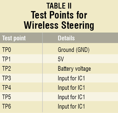
Check the correct input supply at TP1 with respect to TP0. The battery voltage can be verified at TP2. Monitor TP3 through TP6 as you tilt the steering in one direction to confirm that the steering is generating codes corresponding to the movements.
Testing of the robot
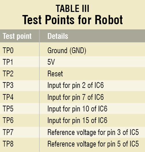
Verify correct power supply to the robot at TP1 with respect to TP0. Proper reset to the microcontroller can be verified at TP2 using an oscilloscope. Make any movements with the steering and check the changes at TP3 through TP6 to confirm that correct actions are initiated by the microcontroller after receiving the code. Reference voltage for the obstacle detection system can be checked and adjusted using TP7 and TP8.
The author is a B.Tech in electronics and communication from Lovely Professional University


which range this project can be operate on?
You can operate the robot from a distance of 30 metres or more, depending on the type and quality of RF module used. Use recommended antenna at RF transmitter and RF receiver module for longer range.
Sir please can u give me this project report on [email protected]