Light emitting diodes are advantageous due to their smaller size, low current consumption and catchy colours they emit. Here is a running message display circuit wherein the letters formed by LED arrangement light up progressively. Once all the letters of the message have been lit up, the circuit gets reset.
 The circuit is built around Johnson decade counter CD4017BC (IC2). One of the IC CD4017BE’s features is its provision of ten fully decoded outputs, making the IC ideal for use in a whole range of sequencing operations. In the circuit only one of the outputs remains high and the other outputs switch to high state successively on the arrival of each clock pulse.
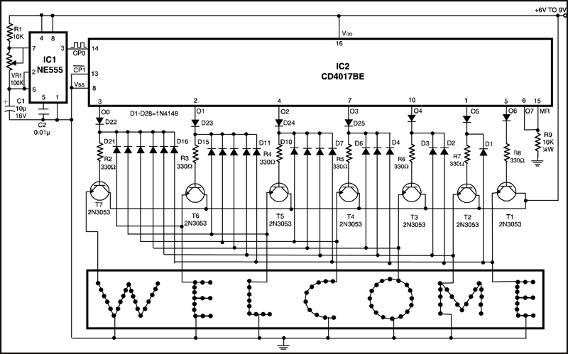
The timer NE555 (IC1) is wired as a 1Hz astable multivibrator which clocks the IC2 for sequencing operations. On reset, output pin 3 goes high and drives transistor T7 to ‘on’ state. The output of transistor T7 is connected to letter ‘W’ of the LED word array (all LEDs of a letter array are connected in parallel) and thus letter ‘W’ is illuminated. On arrival of first clock pulse, pin 3 goes low and pin 2 goes high. Transistor T6 conducts and letter ‘E’ lights up. The preceding letter ‘W’ also remains lighted because of forward. The timer NE555 (IC1) is wired as a 1Hz astable multivibrator which clocks the IC2 for sequencing operations. On reset, output pin 3 goes high and drives transistor T7 to ‘on’ state. The output of transistor T7 is connected to letter ‘W’ of the LED word array (all LEDs of a letter array are connected in parallel) and thus letter ‘W’ is illuminated. On arrival of first clock pulse, pin 3 goes low and pin 2 goes high. Transistor T6 conducts and letter ‘E’ lights up. The preceding letter ‘W’ biasing of transistor T7 via diode D21. In a similar fashion, on the arrival of each successive pulse, the other letters of the display are also illuminated and finally the complete word becomes visible. On the following clock pulse, pin 6 goes to logic 1 and resets the circuit, and the sequence repeats itself. The frequency of sequencing operations is controlled with the help of potmeter VR1.

The display can be fixed on a veroboard of suitable size and connected to ground of a common supply (of 6V to 9V) while the anodes of LEDs are to be connected to emitters of transistors T1 through T7 as shown in the circuit.
The above circuit is very versatile and can be wired with a large number of LEDs to make an LED fashion jewellery of any design. With two circuits connected in a similar manner, multiplexing of LEDs can be done to give a moving display effect.