


Most industrial processes require rotation of the motors in forward and reverse directions for desired periods. One good example is the automated bottle filling plant. Here the bottles move on a conveyor belt. When the bottles come under the filler, the filler comes down (the motor attached with the mechanism rotates forward) and fills the bottle (the motor stops), then it goes up (the motor rotates in reverse direction) and stops until the next bottle arrives. For moving the filler up and down, the time of rotating the motor forward and reverse is calibrated and fixed. Also, the stop time of the motor is calibrated based on the time required to fill the bottle and the time before arrival of the next bottle.
A good domestic application is in washing machines. Once the timer is set to wash clothes, the motor automatically rotates forward and then backward for fixed periods (10 to 15 seconds) with small pauses in between.
As this is a sequential process, a sequential timer can be used to implement it. Sequential timer is a widely used circuit in industrial plants because most industrial processes are chain reaction type. That means as one process ends, it triggers the next. The ending of the last process triggers the first process. Thus the cycle continues.

Generally, such sequence timers are microcontroller-based, multifunctional and programmable. But a very simple sequential timer can be developed using NE555 ICs wired in monostable mode. Cascading a number of these monostable stages forms a sequential timer. The output of one stage is applied as the trigger to the next stage. So when the output of a stage drops, it triggers the next stage and the output of the next stage goes high, and likewise the chain reaction starts. Because here the process involves four steps (forward→stop→reverse→stop), four stages of NE555 ICs connected in monostable multivibrator mode are used to form a four-stage sequential timer. The first stage rotates the motor forward. The second stage stops the motor. The third stage rotates the motor in reverse. The fourth stage stops the motor.
These stages actually energise or de-energise the relays that connect the motor to the supply.
Block diagram
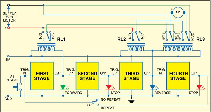
 Fig. 1 shows the block diagram of the sequential timer for DC motor control. The system consists of four blocks of NE555 timer ICs connected in monostable mode. The output of each stage is connected to the trigger input of the next stage. The output of the first stage drives single-changeover relay RL1 and the output of the third stage drives relays RL2 (single-changeover) and RL3 (double-changeover) simultaneously. The second and fourth stages provide delay in between the first stage and third stage outputs.
The LEDs connected at the four stages indicate the status of the motor:
1. In the first stage, the green LED indicates that the motor is running forward.
2. In the second stage, the red LED indicates that the motor has stopped.
3. In the third stage, the blue LED indicates that the motor is running in reverse direction.
4. In the fourth stage, the red LED indicates that the motor has stopped.
The trigger input to the first stage is actually given through process start switch. The output of the fourth stage is fed back to the trigger input of the first stage through the SPDT switch. It decides whether the process continues in loop or one-time only.
Relay connections to the motor are made such that these provide reversible supply to the motor to rotate it forward and backward. As mentioned before, there are two single-changeover relays (RL1 and RL2) and one double-changeover relay (RL3). Connections of relays to the motor are shown in Fig. 1.
Circuit description
Fig. 2 shows the circuit of the sequential timer. The first stage of the sequential timer is built around NE555 IC (IC1). IC1 is wired in monostable mode and its time period is determined by resistor R1, preset VR1 and capacitor C1. Preset VR1 is used to set the time from 4 to 45 minutes. This means you can rotate the motor from a minimum of 4 minutes to the maximum of 45 minutes. Maximum and minimum time limits can be changed by changing the values of the timing components as per the requirement.
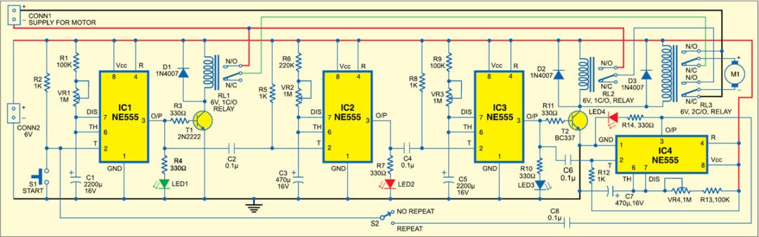
Trigger pin (pin 2) of IC1 is pulled high with resistor R2. When switch S1 is pressed, it goes low and output pin 3 becomes high. The output of IC1 drives transistor T1 into saturation and relay RL1 energises. Also, LED1 (green LED) connected with output pin 3 glows to indicate that the motor is running, say, in forward direction.
The output of IC1 is fed to the second stage through coupling capacitor C2. IC2 (NE555) triggers when the output of IC1 goes low. Diode D1 acts as a free-wheeling diode. The second stage of the sequential timer is made around IC2. This stage provides delay between the first stage and third stage. The red LED connected at the output of IC2 indicates that the motor is in stopped condition.
IC2 too is configured in monostable mode. Its time period is determined by resistor R6, preset VR2 and capacitor C3. Preset VR2 is used to set the time from 1.75 to 10 minutes. If the process requires different timing, the values of timing components can be changed accordingly. The output of IC2 is coupled to the third stage through coupling capacitor C4. IC3 triggers when the output of IC2 goes low.
The third stage of the sequential timer is built around IC3. The timing component values of the third stage are the same as for the first stage because forward rotation time and reverse rotation time should be the same. The only difference is that this stage drives relays RL2 and RL3 simultaneously. Both the relays are connected in parallel and driven by transistor T2. LED3 (blue LED) connected at the output indicates change in the direction of rotation of the motor.
The output of IC3 is coupled to the fourth stage through coupling capacitor C6. The fourth stage of the sequential timer is built around IC4. This stage is identical to the second stage as it also provides delay if the process has to be repeated continuously. If the process completes in a single cycle, this stage is not required. IC4 triggers when the output of IC3 goes low.
Thus with the help of these four timer blocks, the motor first rotates forward (clockwise) for 4-45 minutes, stops for 1.75-10 minutes, rotates in reverse (anticlockwise) direction for 4-45 minutes and then stops for 1.75-10 minutes. The process repeats.
Construction
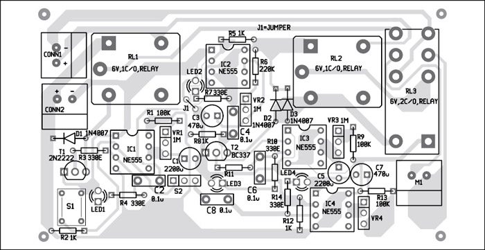
An actual-size, single-side PCB for the sequential timer for DC motor control is shown in Fig. 3 and its component layout in Fig. 4. Assemble the circuit on a PCB as it minimises time and assembly errors. Carefully assemble the components and double-check for any overlooked error. Use proper IC base for the ICs. Before inserting the ICs, check all the supply voltages.
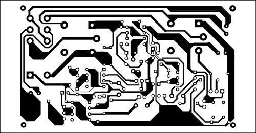
Download PCB and Component Layout PDFs: click here
Connect the 6V power supply to CONN2 and supply for motor to CONN1. Motor M1 should be connected through a connector. Switch S2 should be connected to the PCB through wires.
Now the circuit is ready to use. Press switch S1 to start the motor. Put switch S2 in repeat mode for continuous operation.
The author is a lecturer in electronics and communication engineering department, Government Polytechnic, Amreli.

Can this “sequential logic” be applied to drive a bipolar stepper, since it is a sequential process too? I have seen some signal divider based designs, but can we modify this design, so that first 555 fires the second, second the third, etc. So the coils are energies at correct sequence (of course with an amplifier in between)?
Good idea
Yes it can be used to rotate stepper motor
But not bipolar. It should be unipolar stepper motor
nice info……Thanks, keep it up
You are most welcome.