


The main feature of this transmitter is that it is free from the LC (inductor, capacitor) tuned circuit and operates on a fixed frequency of 12 MHz which is extremely stable. An LC based tuned circuit is inherently unstable due to drift of resonant frequency on account of temperature and humidity variations. The circuit is very simple and uses only a few components.
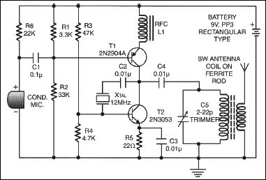
The figure shows the complete circuit diagram of the transmitter. Resistors R1 and R2 are used for DC biasing of transistor T1. The capacitor C1 provides coupling between the condenser microphone and the base of transistor T1. Similarly, resistors R3, R4 and R5 provide DC biasing to transistor T2.

The oscillator section is a combination of transistor T2, crystal XTAL, capacitor C2, C3 and resistors R3, R4 and R5. The crystal is excited by a portion of energy from the collector of transistor T2 through the feedback capacitor C2. The crystal vibrates at its fundamental frequency and the oscillations occurring due to the crystal are applied to the base of transistor T2 across resistor R4. In this way, continuous undamped oscillations are obtained. Any crystal having the frequency in short wave range can be substituted in this circuit, although the operation was tested with a 12 MHz crystal. Transistor T1 serves three functions:
1. It provides the DC path for extending +VCC supply to transistor T2.

2. It amplifies the audio signals obtained from condenser microphone.
3. It injects the audio signal into the high frequency carrier signal for modulation.
The condenser microphone converts the voice message into the electrical signal which is amplified by transistor T1. This amplified audio signal modulates the carrier frequency generated by transistor T2. The amplitude modulated output is obtained at the collector of transistor T2 and is transmitted by a loop antenna into space in the form of electromagnetic waves. The antenna can be tuned to a particular frequency varying trimmer C5 and also by changing the length of ferrite rod into the coil.
The transmitted signals can be received on any short wave receiver without distortion and noise.
