


 The integrated circuits (ICs) 74xx04 and 74xx14 are very frequently used and reused during circuit design. Here xx stands for HC, HCT, AC and LS, etc. Sometimes, the internal inverters of these ICs get damaged. So, it is very important to test these ICs before initiating any experiment and sometimes during the experiments.
Presented here is a simple circuit which can test these ICs statically and dynamically.
Circuit and working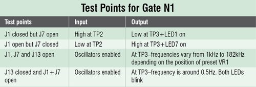 Fig. 1 shows the circuit diagram of a simple tester for 74xx04 and 74xx14 ICs. The circuit is built around hex inverter IC 74HC04 (IC1) and a few other components. You can also test a 74HC14 hex Schmitt trigger with this circuit.

Static testing. The jumpers J1 through J12 are used during static testing of the inverter IC. When J1 through J6 are closed, J7 through J12 should be kept open, and vice versa. When jumpers J1 through J6 are closed, the input of the corresponding inverter is high and the respective output is low. Then, LED1 through LED6 will glow. If jumpers J7 through J12 are closed, the input of the corresponding inverter is low and the respective output is high. Then, LED7 through LED12 will glow. If any one of the LEDs does not glow, it means that the corresponding gate is damaged.
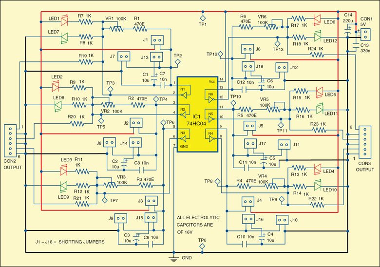
Dynamic testing. During dynamic testing, jumpers J1 through J12 should be kept open. When jumpers J13 through J18 are closed, oscillations are generated on the output of each gate. The frequency varies from 0.5Hz to 10Hz. Here, both the LEDs will blink alternately. Their blinking frequency can be changed with VR1 to VR6, if needed.

 If a gate’s (say, N2) output LEDs do not glow, it means that the gate’s (N2’s) segment is damaged.
IC 74xx04 may not oscillate during dynamic testing because it does not have specified internal Schmitt triggers. So, only IC 74xx14 can be checked dynamically. If all LEDs blink alternately, it means your 74xx14 is fine.
The circuit works on a 5V power supply but you can use a higher voltage supply, within limits specified in the datasheet.
Construction and testing
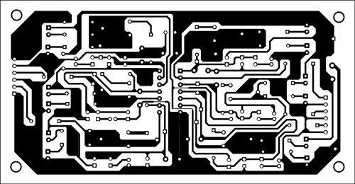
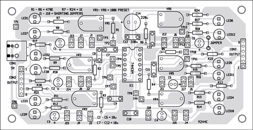
An actual-size, single-side PCB for the simple tester using a socket for the 74xx04 and 74xx14 ICs is shown in Fig. 2 and its component layout in Fig. 3. After assembling the circuit on PCB, enclose it in a suitable plastic case.
Fix two 6-pin connectors CON2 and CON3 for six outputs. Also fix 2-pin terminal connector CON1 for power supply. Jumpers J1 through J18 are used for external shorting. You have to use eighteen 2-pin berg strip male connectors on the PCB for shorting the jumpers. Fix presets VR1 through VR6 on the PCB for frequency control.
Download PCB and component layout PDFs: click here
If you want to test an IC, insert it in the 14-pin IC socket. Connectors CON2 and CON3 are provided on the PCB for testing the voltages at each individual gate. Before inserting IC in its socket, verify the test point voltages given in the table (only for inverter gate N1 given here). Similarly, you can verify other internal gates at the respective test points shown in the circuit diagram as well as in the PCB.
The author was a researcher and assistant professor in Technical University of Sofia (Bulgaria) and an expert-lecturer in OFPPT (Casablanca), Kingdom of Morocco. Now he is working as an electronics engineer in the private sector in Bulgaria
