 Presented here is a circuit for raising an alarm on detecting smoke or LPG cooking gas leakage, or even alcohol vapours in breath. This detection alarm is achieved by using a basic unit with different sensors for smoke, LPG and alcohol. So, different alarms can be made by simply changing the input sensor.
 Detection alarm circuit and working
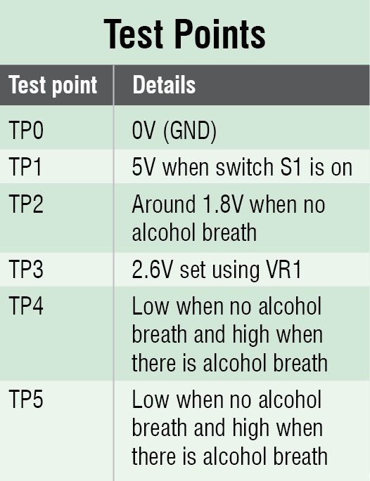
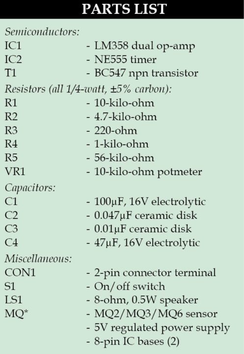
Fig. 1 shows circuit diagram of the smoke detection alarm. The basic unit employs dual op-amp LM358 (IC1), transistor T1 and timer NE555 (IC2), configured in astable mode. Selection of MQ* sensor is based on the purpose for which the alarm circuit is being designed. For the smoke alarm circuit, you will need MQ2 sensor. Similarly, for detection of alcohol, MQ3 sensor is used, while MQ6 sensor is used for detecting LPG cooking gas.
MQ* sensor has six pins. Heater filament, between pins H-H, is directly connected to 5V and ground. Two sets of input/output (I/O) pins A-A and B-B are present. Select any one set for input to the basic unit. Arrangement of pins is shown in Fig. 1.
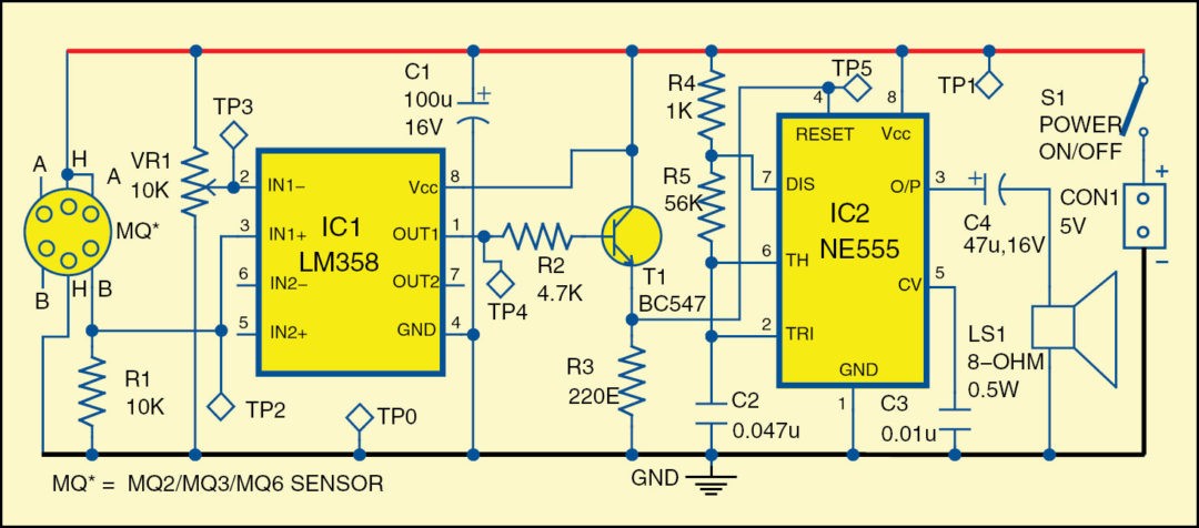
 IC1 is wired in the non-inverting comparator mode. The reference voltage is applied to inverting input (IN1-) and the voltage to be compared is applied to non-inverting input (IN1+). Whenever voltage to be compared (IN1+) goes above reference voltage (IN1-), output of the op-amp swings to high, and vice-versa. The alarm circuit is built around NE555. The frequency of the astable multivibrator is dependent on the values of resistors R4 and R5, and capacitor C2.
After connecting to 5V supply, wait for about ten seconds for the filament to heat properly. Adjust 10k potmeter (VR1) till the alarm stops sounding.
Under normal conditions (that is, no fumes from LPG or no alcohol in breath near MQ*), output of IC1 at pin 1 remains low. As a result, transistor T1 does not conduct, which makes pin 4 of IC2 low. It keeps timer NE555 on reset. There is no output at pin 3 of IC2, and no sound comes out of the speaker.
On the other hand, when there are fumes from LPG, or there is alcohol in breath near MQ*, output of IC1 at pin 1 goes high. As a result, transistor T1 drives into saturation and its emitter goes high. Pin 4 of IC2 also goes high. The timer goes into astable mode, producing pulsed wave at output at pin 3 of IC2, which is coupled to speaker LS1 through coupling capacitor C4, and an alarm is set on.
Download PCB and component layout PDFs: click here
Construction and testing
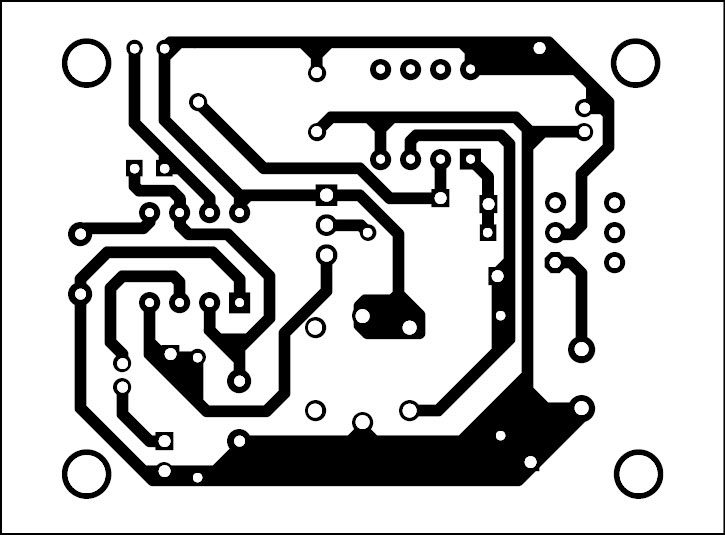
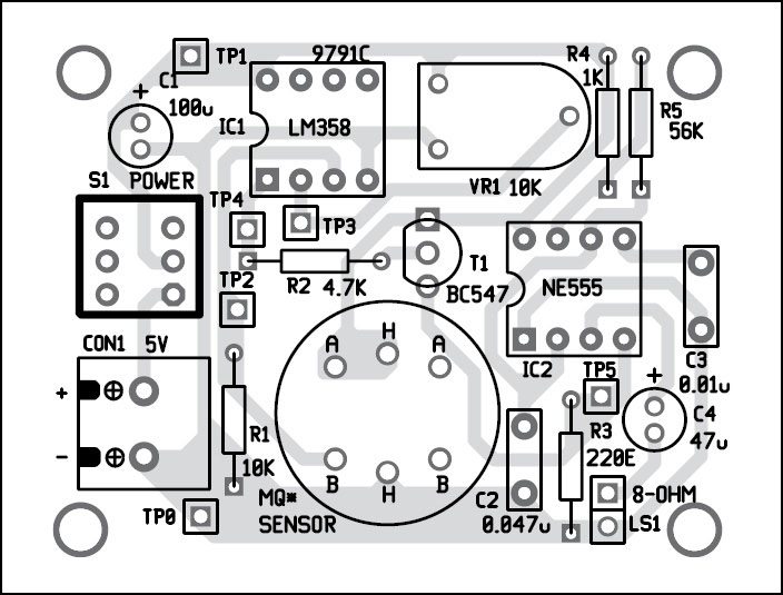
A single-side PCB for the alarm is shown in Fig. 2 and its component layout in Fig. 3. Enclose the PCB in a suitable box, in such a way that fumes can circulate near MQ* sensor easily. Ensure proper wiring to avoid any errors. Before using the circuit, use MQ3 sensor to verify test points given in the table.
EFY note. The circuit was tested successfully with MQ3 alcohol sensor.
Check other related Projects:The author is B.Sc. (Physics) and a regular contributor to international magazines
- LPG Gas Leakage Detection using Arduino
- Gas Leakage Alarm
- LPG Leakage Detector Without a Microcontroller
The author is B.Sc. (Physics) and a regular contributor to international magazines


 Detection alarm circuit and working


not working
The circuit is fully verified by our team. Please recheck your connections.
What amount of smoke is required?
Can you please give me the purpose of each cappacitors and resistors used in this circuit.
Sir ,can u please explain about each component in these circuit?SMOKE ALCHOL AND LPG DETECTION ALARM
What is that cappacitor C1 if for…?? Insted of that 100 uf ceramic disk can i use 47 uf electrolytic..??
Is MQ6 sensor is used for smoke detection
is this circuit working??? please let us know.
Hi Vaishnavi, the circuit is fully verified by our team and working properly.
Yeah, It works. Thanks a lot EYF Team.
You are most welcome.
This circuit works with MQ2 sensor as well. I already tested and working without any errors. Thank you very much.
my buzzer is buzzer is off, what i have to do to fix it ?
Shall I drive a relay instead of 555based alarm after lm358?
Is it works with mq5 sensor?
Where is the Transistor in PCB Layout ?
Transistor T1 (BC547) is shown in the PCB layout between IC1 and IC2