


 Here is a solidstate remote control switch which uses readily available electronic components. The control circuit comprises the transmitter and receiver sections. The range of the transmitter is around seven metres.
The transmitter circuit (shown in Fig. 1) is built around a timer IC (555) wired as an astable multivibrator. It works off a 9V battery. When remote control switch S1 is pressed, the astable multivibrator built around IC1 starts oscillating at a frequency of about 38 kHz. The signal frequency at output pin 3 of IC1 is transmitted through two infrared diodes (IR LED1 and IR LED2). A green LED (LED1) connected to pin 3 glows whenever S1 is pressed, indicating the presence of a signal for transmission at the output of the multivibrator.
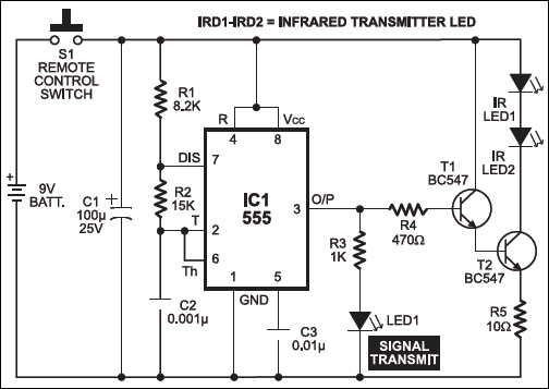
The output frequency F at pin 3 of IC1 depends on the timing components, viz, resistors R1 and R2 and capacitor C2. It is given by the following relationship:

F = 1.443/(R1+2R2)C2
This frequency is fed to npn transistors T1 and T2 (each BC547) through resistor R4 (470-ohm) to drive the IR LEDs. Resistor R5 limits the current flowing through the IR LEDs.

The receiver circuit (shown in Fig. 2) consists of regulator IC 7806 (IC4), IR receiver module (TSOP1738), timer 555 (IC2) and decade counter CD4017 (IC3). Timer 555 (IC2) is wired as a monostable multivibrator.
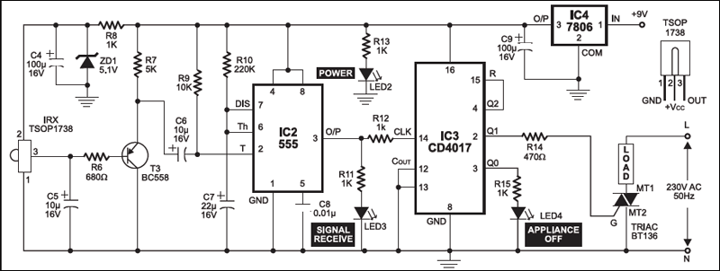
The 9V DC power supply for the receiver circuit is regulated by regulator IC 7806. The presence of power in the circuit is indicated by glowing of the red LED (LED2).
The IR receiver module (TSOP1738), which gets 5.1V power supply through zener diode ZD1, receives the transmitted signal of about 38 kHz. The signal is amplified by transistor BC558 (T3) and given to triggering pin 2 of IC2 through coupling capacitor C6.
Initially, when no signal is received from the transmitter, the output of the IR receiver module is high (approx. 5V).
When the transmitter is pointed at the receiver and switch S1 is momentarily pressed, the transmitted IR rays are sensed by the receiver module and its output pulses low to trigger the monostable (IC2). The output of IC2 goes high for about five seconds. Thus, even if you press the remote switch more than one time by mistake, there won’t be any change in the output of the receiver within this period and hence no undesired switching of the appliance. The signal reception is indicated by glowing of the green LED (LED3).
The output of IC2 is given to the clock input (pin 14) of IC3. Here, IC3 is wired as a bistable circuit. For every clock input, pins 2 and 3 of IC3 alternately go high.
Initially, when the power to the receiver circuit is switched on, pin 3 of IC3 is high and therefore the yellow LED (LED4) connected to it glows. The glowing of LED4 indicates that the appliance is in ‘off’ condition.
When a clock pulse is received at pin 14 of IC3, pin 3 goes low to turn off LED4 , while pin 2 becomes high. The high output at pin 2 triggers the gate of triac BT136 , which ,in turn , contrils the appliance.
Precautions. Don’t touch the leads of the triac as it is connected across the 230v AC mains. Also, make sure that the netural point of mains is connected to the ground line of the circuit and not vice versa.

Good
I want to best in this way help me
Kindly elaborate your query.