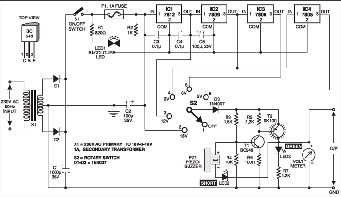
 Here is an efficient 4-stage stabilised power supply unit for testing electronic circuits. It provides well regulated and stabilised output, which is essential for most electronic circuits to give proper results. The circuit provides an audio-visual indication if there is a short circuit in the PCB under test, so the power supply to the circuit ‘under test’ can be cut-off immediately to save the valuable components from damage.

The circuit provides four different regulated outputs (12V, 9V, 6V and 5V) and an unregulated 18V output, which are selectable through rotary switch S2. The selected output is indicated on the analogue voltmeter connected to the outputs rails.
The circuit uses a standard 18V-0-18V, 500mA step-down transformer to generte 18V AC. A rectifier diode comprising diodes D1 and D2 provides 18V DC, which is smoothed by capacitor C1 and given to the combination of regulator ICs (IC1 through IC4). The regulator ICs produce fixed, regulated outputs of 12V, 9V, 6V and 5V, respectively, which are connected to the rotary switch contacts. This power supply is useful for loads requiring up to 200mA current.
Complementary transistors T1 and T2 conduct when the power to the circuit is switched on. Full selected supply voltage is available at the collector of transistor T2, which is used to power the load. LED3 indicates the presence of output voltage. The negative terminal of piezobuzzer PZ1 is connected to the output rail via LED2, so the piezobuzzer remains silent as its negative terminal is also at full supply voltage (selected). If there is a short circuit at the output, LED2 glows to activate the piezobuzzer.
A fuse-failure indicator distinguishes short circuit at the output and input failure. It consists of a bicolour LED (LED1) and resistors R1 and R2. When power is available and the fuse is intact, red and green halves of LED1 are effectively in parallel to output a yellowish light. When fuse fails, green LED goes off and red LED lights up to indicate fuse breakdown.
The circuit can be easily constructed on a general-purpose PCB. Use small heat-sinks for all ICs to dissipate heat. The output voltage can be read on a voltmeter. Enclose the circuit in a metal box with provisions for voltmeter, LEDs, rotary switch, etc.


pcb layout please
Will the buzzer continuously beeps during short