Construction and testing
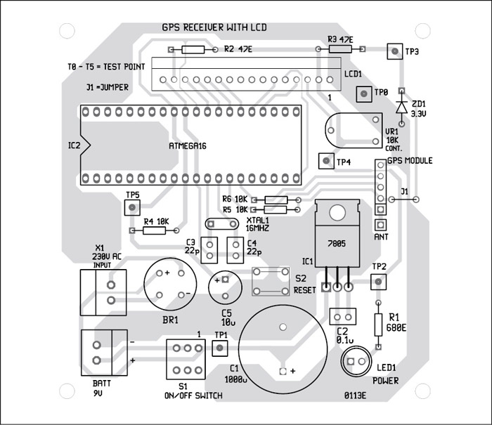
An actual-size, single-side PCB layout of the standalone GPS receiver with LCD display is shown in Fig. 4 and its component layout in Fig. 5.
Testing is relatively simple and user-friendly. When you connect 9V power supply to the circuit, LED1 glows, indicating the presence of power supply in the circuit. Wait for some time, say, 5 to 10 minutes, for initialisation of the GPS module.

If everything is fine, you will receive the latitude and longitude right on the LCD screen. Otherwise, switch off the circuit and switch on again, wait for some time and repeat the above steps. You can also press switch S2 momentarily to reset the circuit.
To help you troubleshoot the problems, test points (TP0 through TP5) are indicated in the circuit (Fig. 2). Their details are given in the table.
First, check proper power supply at TP1 with respect to TP0. You should get 9V in your voltmeter. Next, check the voltage at TP2. If you don’t get 5V, either 7805 is faulty or there is some connection problem (short or open) in the circuit. Next, check 3.3V at TP3. Otherwise, check the zener diode value and connection. Next, at TP4, check 5V supply for the LCD. Vary the LCD contrast control by turning the preset wiper right and left. Next, check the voltage at TP5. It should be 0V when S2 is pressed, otherwise 5V.
If you still face any problem, please refer to the ‘PC-Based GPS Receiver’ project published in EFY Oct. 2012 issue. If you are getting proper data on your PC, you will get the same in this project also, provided the gpss.c program is loaded correctly.

Download PCB and Component Layout PDFs: click Here
Download Source Code: Click Here
Once you have the coordinates on your screen, you can pick up a world map and locate the place yourself. In case you want to see the exact standard time, refer to the time obtained in this application, which entirely depends on satellite navigation.
Sani Theo is a B.Tech in electronics & communication engineering and Prince Gupta is a third-year B.Tech (electrical engineering) student at IIT, Rajasthan


Very good project indeed.
Want to know, how the satellite data is received by the GPS module?
Also where can I get the EFY Dec. 2011 issue? or any link?
Thanks for the feedback! Some details of the GPS module can be found from here :http://www.iwavejapan.co.jp/product/iW%20pdf%20files/iW-GPS-01b.pdf More detail can be found from its datasheets. You can get back issues of EFY from our online stores like efymagonline.com, magzter.com, pothi.com, lulu.com, amazon.com, etc