


 This system needs to be attached to an existing car stereo amplifier to add extra ‘boom effect’ to the music. It has a dedicated loudspeaker with a power amplifier to boost low frequencies that are normally omnidirectional.
The power amplifier used is an integrated class-B output amplifier in a 17-lead single-in-line (SIL) power package. It contains 4×12W single-ended (SE) or 2×24W bridge-tied load (BTL) amplifiers. The output speaker is connected in BTL configuration in this system for better quality.
Circuit and working
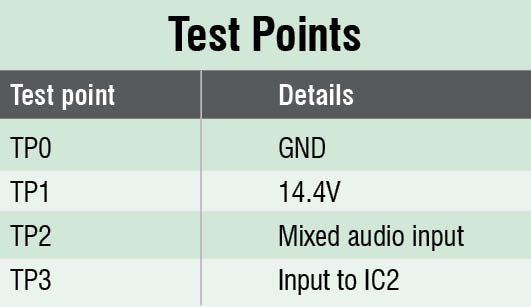 Fig. 1 shows the circuit diagram of subwoofer for cars. It is built around low-noise JFET-input operational amplifiers TL072 (IC1), car radio power amplifier TDA8561Q (IC2) and transistors BC547 (T1 and T2). IC2 has two 24W BTL output channels, one of which is connected to loudspeaker LS1. BTL is an output configuration for audio amplifiers, a form of impedance bridging where two channels of a stereo amplifier are fed the same audio signal, with one channel’s electrical polarity reversed. Such an arrangement can double the voltage swing at the load.

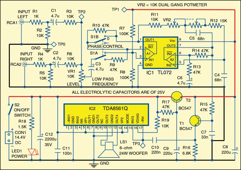
Both channels from the car stereo are fed to the system through connectors RCA1 and RCA2. Audio from both the channels is mixed after level control. After mixing, the signals are fed to the buffer stage implemented with op-amp A1 of IC1 and the output phase can be reversed using switch S1A and S1B. This control can be useful to allow the subwoofer to be in phase with the loudspeakers of the existing car radio.
 A 12dB octave variable frequency low-pass filter (LPF) built around op-amp A2 of IC1, transistor T1 and related components allows to adjust precisely (using dual-gang potmeter VR2) the low-pass frequencies between 70Hz and 150Hz. Resistor R17, capacitor C9 and transistor T2 form a simple DC voltage stabiliser for the input and filter circuitry. The filtered output is fed to inputs INV3 and -IN4 of power amplifier IC2, and the amplified output can be heard at LS1. The power supply of the circuit is 14.4V obtained from car battery. The logarithmic potmeter VR1 is used to control volume level.

Construction and testing
A single-side PCB for the subwoofer is shown in Fig. 2 and its component layout in Fig. 3. After assembling the circuit on PCB, enclose it in a suitable plastic case. Use suitable heat sink for IC2.
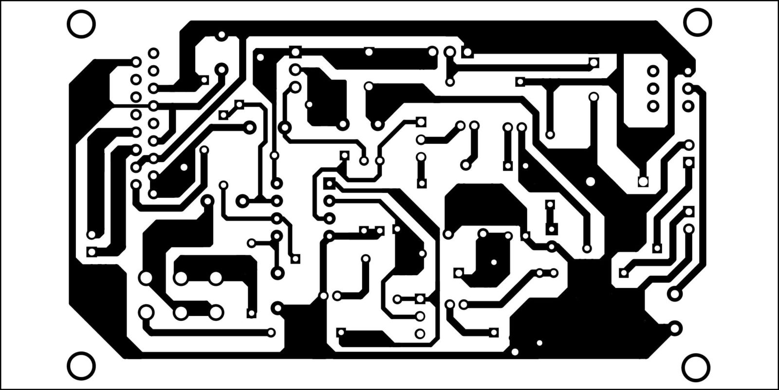

Download PCB and component layout PDFs: click here
Fix 2-pin connector for connecting 8-ohm, 24W woofer LS1 and connect the power supply at CON1. The left and right stereo channels are to be connected to RCA1 and RCA2 through external wires. Ensure that VR1 and VR2 are accessible from outside for volume and LPF frequency control. Use voltage levels mentioned in the test points table for debugging, if required.
The author is a B.Tech (ECE) from Prasad Institute of Technology, Jaunpur, UP. He is currently working in ESP Safety Pvt Ltd, Delhi as a senior hardware R&D engineer


Sir what is the size of pcb layout please tell me I wants to make this amplifier
Sir, Can i use TDA2050 IC. Please ?
You cannot use TDA2050 IC directly here because this IC is available in pentawatt vertical package whereas TDA8561Q used here is in SIL package. To replace TDA8561Q with TDA2050 would require different circuit design and PCB.
what is TP0,TP1,TP2TP3?
TP0,TP1,TP2 and TP3 are test points in the circuit. You can check at these points with multimeter when you have problems in the circuit.
How to check tp2 &tp3 with multimeter…
What to check for it ac mode or ac mode for multimeter
Liked it very much ?
Please share some more car subwoofer amplifier circuits
Dear sir
Tl 072 ic circuit not working audio signal not out . Pin 6&7
Plz halp …….