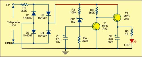
 This circuit gives a visual indication of whether a telephone line is in use or not, helping two or more people sharing the line to avoid interrupting each other’s calls. As the circuit connects in parallel with the telephone line, it can also detect phone tapping/misuse attempts. The circuit draws negligible current from the telephone line for its operation.
Fig. 1 shows the circuit of the telephone line indicator. When the telephone is not in use (the handset is on hook), the line voltage is 48-60V. This voltage passes through the simple polarity guard built around the bridge rectifier comprising diodes D1 through D4 and fed to the remaining circuit. Zener diode ZD1 breaks down and transistor T1 conducts. As a result, transistor T2 does not conduct and LED1 does not glow, indicating that the line is not in use.

When the telephone line is in use (the handset is off-hook), the line voltage drops to a level below the zener voltage of ZD1. Transistor T1 cuts off and transistor T2 conducts. As a result, LED1 lights up to indicate a busy/in use/tap/misuse condition.
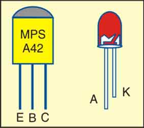
Assemble the circuit on a general-purpose PCB and enclose in a suitable cabinet. Refer Fig. 2 for the pin configuration of transistor MPSA42 and LED.


Hi,I’m new to electronic,
an on T1 VBEO are above 8v with this design with an input at 48vdc, the MPSA42 spec from FAIRCHILD , is at VBEO Max absolute rating is at 6v.
maybe I’m missing something here (please explain the design R2,ZD1,R4,T1)
let me know if this make sense.
Thank you