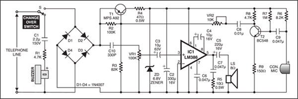
This simple telephone receiver without a dialing section can be connected in parallel to a telephone line. It can be easily assembled on a small veroboard or a PCB. A geometry box made in the shape of a telephone receiver will be an excellent cabinet for it. No external power supply is needed, which makes the circuit handy.
Telephone Receiver Circuit

The ringer section comprises R1, C1, and a buzzer. If your telephone has a loud ringer, this circuit can be avoided. A bridge rectifier consisting of diodes D1 through D4 protects the circuit from any polarity change in the telephone line. PNP transistor MPS-A92 (T1) is the main interface transistor. The output of T1 is regulated by zener diode ZD and capacitor C2 to get 6.8V for powering the amplifier section. This power is also used to bias the transmitter section.
The transmitter section comprises transistor BC548 (T2) together with a few discrete components and a condenser microphone. The transmit signal is fed to the base of interface transistor T1. The voice input for the amplifier comes directly from the positive end of the bridge rectifier.
The amplifier section is built around high-performance, low-wattage power amplifier IC LM386. This circuit is designed as a high-gain amplifier. A small 8-ohm speaker is good enough for the output.
After all soldering is done, adjust presets VR1 and VR2 to their middle position and connect the circuit to the telephone line in parallel. Adjust VR1 and VR2 for optimum reception as well as transmission.
The article was first published in January 1997 and has recently been updated.


hello,
does this circuit provide voice feedback from the microphone to the speaker to hear oneself voice also?
Yes it give you feedback
do you reply or just post my comment to make this page popular?
Dear Jim,
For all projects related query, the comments are forwarded to the concerned team. They take up those comments and check for errors (If any) and reply accordingly.
Dear Sir
Would this circuit hold the line on it’s own if used in the U.K. or would you always have to pick up with the official Telephone and keep it off the hook while this circuit was being used?
This should work well in UK also. You need to pick up the handset to start a conversation with the caller.
Hello, my name is Lucas, I am from Brazil.
First of all, thanks for providing this circuit and congratulations for this website.
I have a doubt: is it possible to change the switch for a flip flop T circuit in a way that I could a tactile switch?
Thanks!
How to conect external speaker to the telephone
hi no working!!!!!!!!
Kindly elaborate your query.
I made it, I connect it to the telephone line and only noise is heard, no sound at all !!
Dear Kas,
Thank you for posting your query in electronicsforu.com
Follow these steps to rectify the problems.
1. Check the connections properly.
2. After connecting the telephone line keep the changeover switch S towards bridge side
3. Check the voltage across cathode of ZD,it should be 6.8V
4. Replace the LM386.
5. Keep VR1 and VR1 in middle.
6. Once this is done, hope circuit should work
If you have any further queries, feel free to contact us. We will be happy to help you.
Thank you.