 We the humans can hear sound of up to 20kHz frequency only. This proximity detector works at a frequency of 40 kHz. It uses two specially made ultrasonic transducers: One transducer emits 40kHz sound, while the other receives 40kHz sound and converts it into electrical variation of the same frequency.

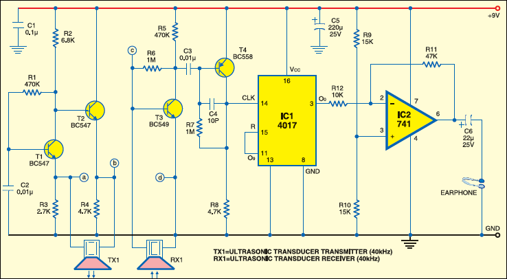
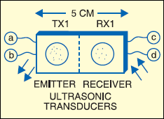
Fig. 1 shows the block diagram of the ultrasonic proximity detector and Fig. 2 shows its circuit. Mount the transducers (transmitter as well as receiver) about 5 cm apart on a piece of general-purpose PCB as shown in Fig. 3 and connect to identical points (‘a’ through ‘d’) of the detector circuit (Fig. 2) via external wires.

The 40kHz oscillator is built around transistors T1 and T2. If there is a solid object in front of the ultrasonic transmitter module (TX1), some signals will be reflected back and sensed by the receiver transducer (RX1). The 40kHz ultrasonic signals are converted into 40kHz electric signals by the receiver and then amplified by transistors T3 and T4.
The amplified signals are still in the inaudible range, i.e., these can’t be heard. So a frequency-divider stage using CMOS decade counter IC4017 (IC1) is used at the output of the amplifier. IC1 divides the input frequency by ’10,’ so the 40kHz signal becomes 4 kHz, which is within the audible range. The 4kHz signals are fed to op-amp IC 741 (IC2), which is wired as an earphone amplifier.
This circuit can be used as an electronic guard for the blind. Keep it (along with 9V battery) in their pocket with earphone plugged to their ear. The transducer modules should be directed towards the walking path. If any object comes up in front or nearby, they will hear 4kHz sound through the earphone and can change their path accordingly.
One thing to be noted here is that while using this device, avoid the company of your pets. The reason is that pets can hear ultrasonic sound, which will irritate them and they will bark unnecessarily.

EFY note. A similar device is used in some cars, such as Skoda’s Laura model, to help the drivers in backing up and avoid banging against some


by connecting same circuit diagram we didnt get output .if any could help me pls reply
Comment:i can’t get out put please help me….!
can we use this circuit for making an ultrasonic sensor, if it is possible means please tell me how to make ultrasonic sensor.
Otherwise tell me can i use any ultrasonic sensor with this circuit.