


 A voltage regulator (also called a ‘regulator’) with only three terminals appears to be a simple device, but it is in fact a very complex integrated circuit. It converts a varying input voltage into a constant ‘regulated’ output voltage. Voltage regulators are available in a variety of outputs like 5V, 6V, 9V, 12V and 15V.
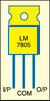
The LM78XX series of voltage regulators are designed for positive input. For applications requiring negative input, the LM79XX series is used. Fig. 1 shows the pin configuration of a 5V 7805 regulator.
The output voltage of a regulator circuit can be increased by using a pair of ‘voltage-divider’ resistors. It is not possible to obtain a voltage lower than the stated rating. You cannot use a 12V regulator to make a 5V power supply, but you can use a 5V regulator to make a 12V supply.

Voltage regulators are very robust. These can with stand over-current draw due to short circuits and also over-heating. In both cases, the regulator will cut off before any damage occurs. The only way to destroy a regulator is to apply reverse voltage to its input. Reverse polarity destroys the regulator almost instantly.
Fig. 2 shows the circuit for increasing the output voltage of a regulator circuit using a pair of voltage-divider resistors. Let’s assume the value of R1 as 470 ohms, which means that a constant current of 10.6 mA will be available between terminals 2 and 3 of 7805. This constant current plus the regulator standby current of about 2.5 mA will flow through R2 to ground regardless of its value. Because of this constant 13.1mA current, R2 can now be set to a value that will give constant 7 volts across resistor R2. A resistor value of 533 or 510 ohms (standard value) will give the necessary 7 volts.

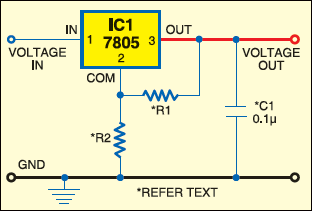
With 5 volts across R1 and 7 volts across R2, a total of about 12 volts (regulated) will appear across terminal 2 and ground. If a variable resistor is used as R2, the output voltage can be easily fine-tuned to any value greater than 5 volts. The standby current will vary slightly in the regulator 7805, but 2.5 mA will yield good results in the calculations. If an exact voltage(within 0.3 volt) is needed, R2 must be a variable resistor. To make any fixed regulator adjustable, use the following formula:
Vout=Vfixed+R2 (Vfixed/R1+Istandby)
where Vout is the desired output voltage, Vfixed is the fixed voltage of the IC regulator (5 volts) and Istandby is the standby current of the regulator (2.5 mA). For resistor R1, use any value from 470 ohms to 1 kilo-ohm for best results. For variable resistor R2, put any value from the table given here for desired voltage operation.
Fig. 3 shows the circuit of a 6V-12V variable power supply using a 5V regulator. The 220V AC mains voltage is stepped down by transformer X1 to 9 volts, rectified by the bridge rectifier comprising 1N4007 diodes D1 through D4, filtered by smoothing capacitors C1 and C2, and regulated by IC 7805 (IC1). Capacitors C1 and C2 help to maintain a constant input to the regulator.
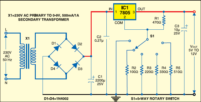
Capacitor C1 should be rated at a minimum of 1000 µF for each ampere of current drawn and at least twice the input voltage. Wire the 270nF or greater disk (ceramic) capacitor close to the input terminal of the IC, and a 10µF or greater electrolytic capacitor across the output. The regulator ICs ypically give 60 dB of ripple rejection, so 1V of input ripple appears as a mere 1 mV of ripple in the regulated output.
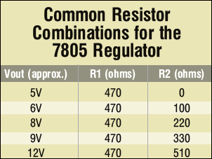
Attach the 5-way rotary switch to resistors of different values to get the regulated output as shown in the table. Or, you can use a 1-kilo-ohm potmeter as a variable resistor to get the regulated 5V-12V output.

Comment:sir send me video
Comment:variable power supply from fixed voltage regulator
What should be the maximum appropriate capacitor value to be used at output of regulator IC for clean output ?