


 Here is a circuit that can be used in offices, stores, warehouses, etc during night to check whether the watchman of your establishment is on duty. For operation, it uses an existing telephone (e.g. in office or store) closest to the watchman’s post. The watchman is given an audio alert signal by just ringing the office/store telephone once (minimum) from your residence or any other place, preferably using your mobile phone. The ring is detected by the given circuit and the watchman is also given a visual alert signal by a glowing lamp. The lamp remains ‘on’ for a duration of nearly 60 seconds soon after the ring tone. The watchman is given an instruction to register his presence by simply pointing his torch-light beam towards a wall-mounted LDR sensor unit (without lifting the handset off-cradle of the ringing telephone). This is to be done within the time period during which the alert lamp glows. If he fails to do it within the permissible time, the circuit registers his absence by incrementing a count. If he does, the count remains unaltered.
Up to nine separate alert rings are considered here. The count displayed is the number of times the watchman failed to register his presence. The mobile phone records the called number and call time, and it can be used with the displayed count to get the timing details.
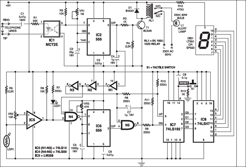

The telephone lines (TIP and RING) Counter 74LS192 (IC7) is reset to zero state by making its reset pin 14 high through reset switch S1. The 7-segment, common-anode display DIS1 is driven through IC 74LS47 (IC8). When the phone rings, count ‘1’ is displayed after nearly one minute. This happens if the watchman fails to focus the torchlight beam on LDR1.
If LDR1 receives light from the torch of the watchman within the allowed time period, the down clock remains high until the up clock is high. The counter counts up and then down, so, in effect, the count remains unchanged.

All components, except LDR1, are kept in a sealed cabinet with locking arrangement. Only LDR1 is wall-mounted and visible outside. This is done to avoid manual resetting of the counter. The circuit is to be powered by a battery to avoid resetting of the count during power failure.
The working procedure can be summarised as follows:
1. Initially, when the power supply is switched on, power-on-reset components C8 and R13 reset counter IC7 and the display shows ‘0.’
2. Now dial the telephone number (where parallel system is installed) from outside or from your mobile. For the first ring, relay RL1 energises and alert lamp L1 glows.
3.When alert lamp L1 is off, the counter is incremented by ‘1.’
4. If the watchman focuses the torch-light beam on LDR1 within the glowing time of alert lamp L1, the counter first counts up and then counts down and finally the display shows 0. This indicates that the watchman is present.
5. If the watchman focuses the torch-light beam on LDR1 after alert lamp L1 goes off, up-counting takes place and the display shows ‘1.’ This indicates that the watchman is absent.

is there a simple circuit similar to this, because i want to do this project, please if there is another circuit please send to my email [email protected]
Plzz show the components or send it to my email [email protected]