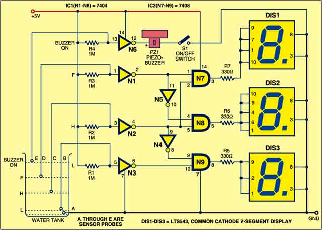
 This water level indicator using 7 segment display indicates the water level (low, half and full) in the tank. A buzzer is added to alert you of water overflowing from the tank. The circuit shows the water level by displaying L, H and F for low, half and full, respectively.
Circuit description
The circuit uses five sensors to sense the different water levels in the tank. Sensor A is connected to the negative terminal (GND) of the power supply. The other four sensors (B through E) are connected to the inputs of NOT gate IC 7404. When there is a high voltage at the input pin of the NOT gate, it outputs a low voltage. Similarly, for a low voltage at the input pin of the NOT gate, it outputs a high voltage.

Circuit operation
When the tank is empty, the input pins of IC 7404 are pulled high via a 1-mega-ohm resistor. So it outputs a low voltage. As water starts filling the tank, a low voltage is available at the input pins of the gate and it outputs a high voltage.
When the water in the tank rises to touch the low level, there is a low voltage at input pin 5 of gate N3 and high output at pin 6. Pin 6 of the gate is connected to pin 10 of gate N9, so pin 10 also goes high. Now as both pins 9 and 10 of gate N9 are high, its output pin 8 also goes high. As a result, positive supply is applied to DIS3 and it shows ‘L’ indicating low level of water in the tank.
Similarly, when water in the tank touches the half level, pins 4 and 5 of AND gate N8 become high. As a result, its output also goes high and DIS2 shows ‘H’ indicating half level of water in the tank. At this time, pin 9 of gate N9 also goes low via gate N4 and DIS3 stops glowing.
When the water tank becomes full, the voltage at pin 1 of gate N1 and pin 3 of gate N2 goes low. Output pin 3 of gate N7 goes high and DIS1 shows ‘F’ indicating that the water tank is full.When water starts overflowing the tank, pin 13 of gate N6 goes low to make output pin 12. The buzzer sounds to indicate that water is overflowing the tank and you need to switch off the motor pump.
Construction
Assemble the circuit on a general purpose PCB and enclose in a suitable box. Use a non-corrosive material such as steel strip for the five sensors and hang them in the water tank as shown in the circuit diagram. Use regulated 5V to power the circuit.
Feel interested? Check out other electronics projects.
Riju Thazhathu Veettil is R&D engineer at Technonics R&D Lab, Malappuram, Kerala


what are those five sensing elements used???
1. one for ground
2. second for partially filled
3. third for full
4. fourth for overflow
5. fifth for empty
The five sensors denoted by A, B, C, D and E are nothing but stainless steel rods.
Why the resistor R1 to R4 are used?please explain
Those are pull-up resistors
how do you use a 3way dip switch plus one +5v supply probe instead of 5?
Can use 12v DC power supply
This project how many components require
Yar bhai log ma na circuit design kiaha proteous py yar waha bss Low hi print hotta ha Half or full nai hotta kuch guaid kr dy agr koi chahy
Kindly write your query in English, please.
are you test this circuit bro
Hi Silva, the circuit is fully tested by our Team.
i want to know, what company use that curcuit to make water level indicator
How do you code this in VHDL Code? Thank You! I was quiet confused in sensor A and E. I don’t know where am I going to connect them when I’m doing a VHDL Code. Thank You again for whoever will answer…
What message or number is shown at each step level.
Okay, I got. Forget my message before
Have you think to upgrade this circuit to control level at same time? Start and Stop pump.