 In large classrooms, many a times the teacher’s voice is not audible to students in the back rows. So the teacher have to literally shout to be heard by every student. Presented here is a Wireless PA circuit that can act as a wireless speech-aid for teachers so that their voice reaches every student even in a large classroom.
The circuit has two parts: wireless microphone and receiver amplifier. Wireless microphone is held by the teacher and whatever he speaks is transmitted over the FM band. Several receivers with speakers can be placed around the room to cover it completely.
Circuit and working of Wireless PA
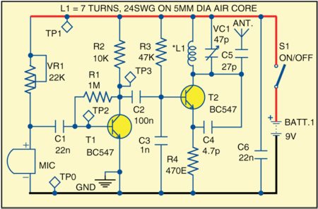
Fig. 1 shows the circuit of wireless microphone. The receiver amplifier circuit is shown in Fig. 2.
Wireless microphone section
The transmitter section of wireless PA for classrooms is built around two BC547 npn transistors (T1 and T2), electret microphone (MIC) and a few other components. The audio signal is picked up by electret microphone MIC and amplified by transistor T1. The amplified output is fed to the base of transistor T2. Here transistor T2 modulates the L-C tank circuit comprising L1 and VC1 due to its varying junction capacitance corresponding to the input signal at the base. The tank circuit closely resembles a Colpitts oscillator. The 27pF capacitor connected with antenna isolates L-C circuit from the aerial capacitance. Inductor L1 is made by winding seven turns of 24 SWG copper wire around a 5mm diameter air core. For antenna, use any flexible wire.
Receiver amplifier section
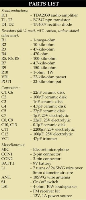
The receiver section of wireless PA for classrooms is built around audio amplifier TDA2030 (IC1), FM receiver kit, loudspeaker (LS1) and a few discrete components. There are many FM receiver kits available with Sony ICs like CXA1019 and CAA1619. There are also some with Philips ICs. FM kits have the option to operate at either 6 V or 12 V. Select 12 V for this project and use a 12V, 1A adaptor for power supply. Select a kit that uses trimmers in place of a gang capacitor. Of course, even a ganged capacitor kit will do. But once the circuit is aligned with the FM transmitter/wireless microphone, it is difficult to fix the gang in a particular position.
The output of the FM kit is connected to the audio amplifier made using IC1. To make IC1 work on a single power supply, a pair of diodes D1 and D2 in conjunction with 100-kilo-ohm resistor R8 is used to create a virtual earth. Heat-sink should be used to prevent shutdown of IC1 due to overheating.
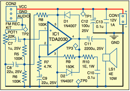
Working of the circuit is simple. Once transmitter and receiver are tuned (see calibration section), the microphone picks up the teacher’s voice and transmits it over the FM band. The FM kit receives the audio, which is further amplified by the amplifier. This amplified audio is available at loudspeaker LS1.
Calibration
Keep the transmitter and receiver sections around three metres apart. First, switch on the receiver and tune it to some fixed frequency that is away from the regular broadcasting channel frequencies. Set volume in the middle position.
Now turn on the wireless microphone with switch S1. With the help of a small plastic screwdriver, turn trimmer VC1 a little at a time (5 degrees maximum) until ‘hissing’ from the radio stops and null point is found. This means that the wireless microphone is now tuned at the same frequency.
Download PCB and component layout PDFs: click here
Place a quartz clock very close to the electret microphone. Now you should be able to hear ‘clicks’ on loudspeaker LS1. The ‘clicks’ sound should be very clear and without noise. If not, use preset VR1 to set the sensitivity and/or spread/compress the coil. Repeat this process two-three times to fine-tune both the circuits. Ensure that the aligned frequency does not interfere with any local FM station.
Construction and testing
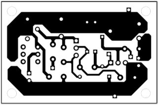
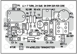
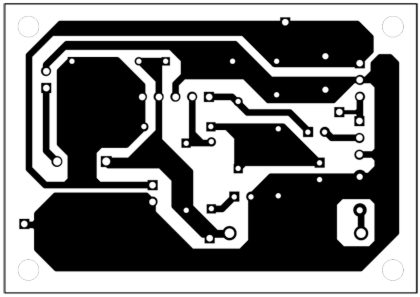
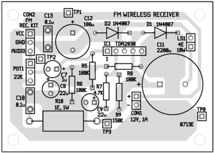
An actual-size, single-side PCB for the wireless microphone is shown in Fig. 3 and its component layout in Fig. 4. PCB for the receiver amplifier is shown in Fig. 5 and its component layout in Fig. 6. Suitable connectors are provided on the PCB for input and output. Assemble the circuits on these PCBs only to minimise errors. Carefully assemble the components and double-check for any overlooked error.
For wireless microphone use a small plastic box that can fit inside your shirt’s front pocket. For receiver use a cabinet suitable for standard speakers. Fix the receiver amplifier inside and connect a 30.5cm (12-inch) long telescopic antenna or an insulated 18SWG wire for antenna.
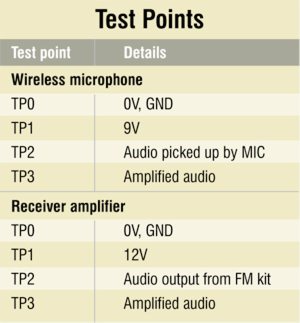
To test the wireless microphone for proper functioning, check correct power supply at TP1 with respect to TP0. Audio picked up by the microphone can be checked at TP2. The amplified audio can be checked at TP3 using an oscilloscope. Similarly, check the receiver amplifier side too for correct voltages and audio signals as per the test point table.
The author is a regular contributor to EFY


Can I please get the video for this circuit …….. So that I can make the circuit more precisely……. I will be very glad if I get the video…..
Sorry, video is not available right now.
CAN U GIVE ME AN IDEA FOR BUILT AN MINI FM STATION AND I HAVE A DOUBT .I.CAN I USE FM RECEIVER AS OUR MOBILE PHONE RECEIVER
Where is the receiver circuit: 🙂
It is present within the article.
yes you’ve mention it in the article but Fig 1 and Fig 2 are the same. Fig 2 which is the receiver circuit has a mic on it.
fig 1 and fig2 are the same where is reciever circuit
Hi Gaston,
Thank you for your comment, we have updated the article.