


This circuit will turn the heater ‘on’ when the temperature of water falls below the lower limit set by you and turn it ‘off’ when the temperature increases above the higher limit.
The circuit works off 12V regulated power supply and comprises bridge and op-amp sections. The bridge section is built around resistors R1 and R2, preset VR1 and resistance temperature detector (RTD). The op-amp section is built around IC1.
At normal temperature of water (say 30°C), the voltage at pin 3 of IC1 is higher than the voltage at pin 2. Thus the output of the op-amp is high and relay driver transistor T1 conducts to energise relay RL1. The N/O contacts of RL1 connect the power supply to the heater. As a result, the heater starts warming up water.

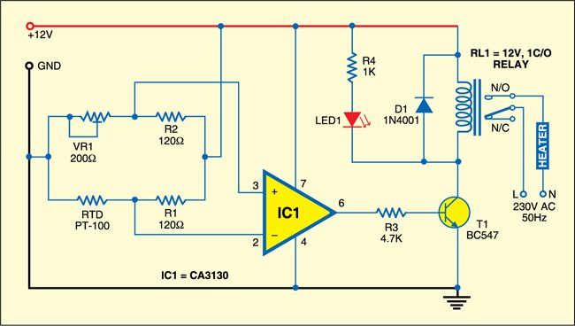
As soon as the temperature of water goes up to, say, 60°C, the voltage at pin 2 of IC1 becomes higher than the voltage at pin 3. Thus the output of op-amp IC1 goes low. Relay driver transistor T1 stops conducting and relay RL1 de-energises. The pole contact with N/C of RL1 disconnects the power supply to the heater and further heating of water stops.

Now when the water temperature goes below the preset level, the relay energises again and connects the heater to the power supply for heating the water. The cycle repeats.
Select the values of resistors R1 and R2 according to your temperature requirements, but these should be such that R1= R2, or proportional. The bridge can be theoretically balanced by measuring the resistance of PT-100 (RTD) for the desired temperature and varying the resistance of the preset.
Also Read:Interesting Electronics Projects
PT-100 has a positive temperature coefficient. That is, its resistance increases as the temperature increases.
For calibration, let’s consider that water is to be heated up to 60°C and has to maintain that temperature. First, heat the water up to 60°C (measure the temperature using a thermometer). Keep sensor PT-100 (RTD) inside water. Keeping RTD at 60°C (as measured by the thermometer), adjust the preset such that the potential difference between the inverting and non-inverting inputs of IC1 becomes negative. That is, when water temperature is 60°C, output pin 6 of IC1 should be low.
Assemble the circuit on a general-purpose PCB and enclose in a suitable cabinet. Connect PT-100 wires to the PCB and dip the metallic part of sensor into water for sensing its temperature.

I need the write up of this project now