


Here is a simple hi-fi audio stereo power amplifier based on TDA2616 IC. This amplifier works on two 12V batteries or one ±12V AC/DC adaptor. The circuit can deliver 2×12-watt output power for 8-ohm loads with ±16V dual-power supply.
Circuit and working
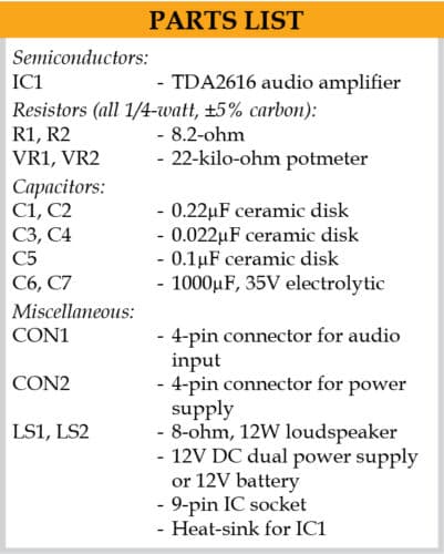
The circuit diagram of the hi-fi audio stereo power amplifier is shown in Fig. 1. The circuit uses IC TDA2616 (IC1), two loudspeakers (L1 and L2) and a few other components. TDA2616 comes in a nine-lead, single-in-line (SIL9) plastic power package.

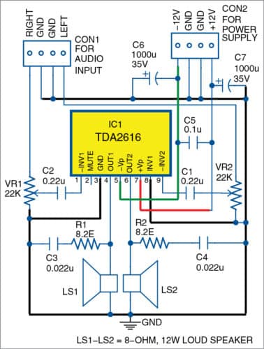
The circuit diagram is straightforward. The left speaker (LS1) is connected to output pin 4 of IC TDA2616, and the right speaker (LS2) is connected to pin 6 of TDA2616. Potmeters VR1 and VR2 are used as left- and right-channel volume controls, respectively. Capacitors C6 and C7 are used as filter capacitors.
Construction and testing
A 5cm x 7cm veroboard may be used for the construction of this project. Alternatively, the PCB layout given in this article can be used. An actual-size PCB layout of the hi-fi audio stereo power amplifier is shown in Fig. 2 and its components layout in Fig. 3.
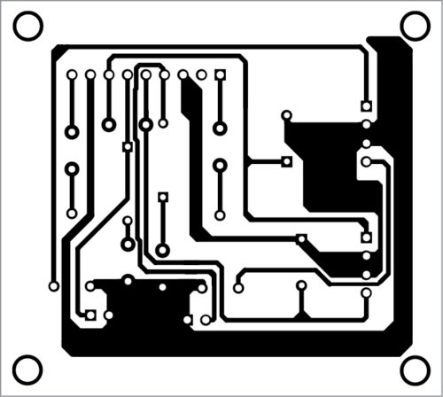
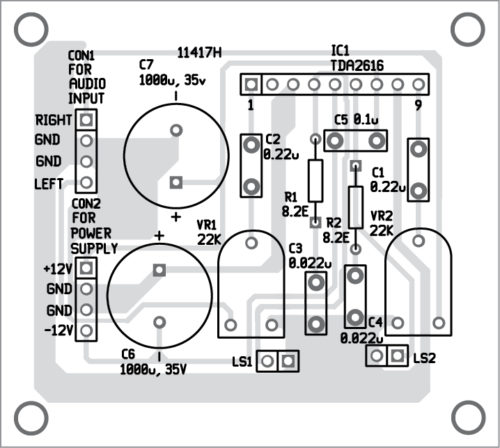
Download PCB and Component layout PDFs: click here
Using an IC socket prevents the IC from being damaged by overheating during soldering. So, a nine-pin IC socket is recommended for TDA2616, besides a suitable-size heat-sink.
After assembling the circuit, enclose it in a suitable box. Fix VR1 and VR2 on the front panel of the box for left and right volume controls, respectively.
Calibration and adjustments
For calibration, take two 12V batteries, and connect the negative and positive terminals to IC1, as shown in the circuit. Now, connect two speakers to the circuit. Set VR1 and VR2 to their middle positions. Take a metal screwdriver and gently touch on input pin 1 or input pin 9 of IC1. You will hear a humming sound from the left and right speakers when the screwdriver is touched at left or right input. Slowly adjust VR1 clockwise until you hear a loud humming sound from the left speaker. Similarly, adjust VR2 for the right speaker. Now, your stereo amplifier is working and ready for use.
Connect audio signal from the audio source such as a cellphone, MP3, laptop or computer to the amplifier using an audio jack. Note that, if pin 2 of TDA2616 is connected to either -12V or GND terminal, it will activate mute function in the circuit.
Raj K. Gorkhali is a hobbyist and a regular contributor to EFY

Nine pin ic socket is not available in market but a dil 9+9 pin is available. But the ic can be directly soldered on the pcb/veroboard after fixing heatsink to it to prevent damage by overheating
Mr. Raj K. Gorkhali, could you please provide me the Gerber file for this circuit?
Please contact at [email protected] to get Gerber file